38 ELECRAFT
i
Since the K2 chassis is made up of a number of individual
panels and fasteners, you may need to loosen the fasteners and
readjust them once or twice during assembly.
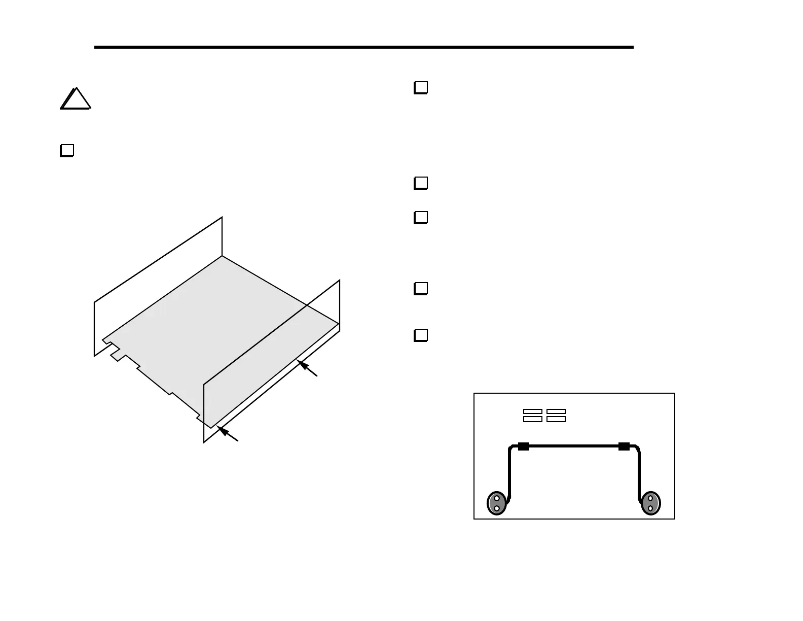
Attach the side panels to the RF board using two chassis screws
per side panel. The side panels are attached to the 2-D fasteners
that are already in place on the RF board. Figure 6-8 shows the
approximate location of the two screws used to secure the right side
panel.
Figure 6-8
Locate the tilt stand, which can be found in the
MISCELLANEOUS component bag. It has three parts: two oval
feet and a tilt bail (Figure 6-9). Note: the screws that will be used to
hold the tilt bail in place are not the black anodized type. They are
standard steel/zinc plated screws, 7/16" (11 mm) long, so you won’t
confuse them with the 3/8" (9.5 mm) or 1/2" (12 mm) black
screws.
Remove any masking tape from the bottom cover chassis
piece.
Each oval foot has a notch into which the bail will be inserted.
Install one of the oval feet on the bottom cover using two 7/16"
(11 mm) 4-40 screws, #4 lock washers, and 4-40 nuts. The notch in
the foot should be facing inwards (toward the other foot). The nuts
and lock washers go on the inside of the bottom cover.
Install the tilt bail, then the second oval foot. The bail should
be compressed firmly between the two feet. You may need to adjust
the positions of the feet slightly before tightening the hardware.
Make sure the two feet are at exactly the same distance from
the front edge of the bottom cover. If they are not equally spaced,
the tilt stand may "rock" when in use.
Figure 6-9