52 ELECRAFT
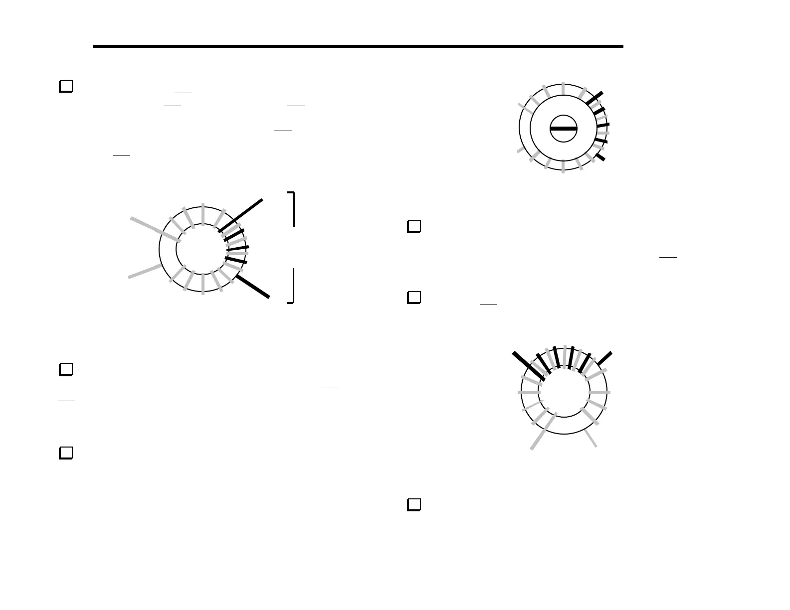
T5’s other winding, 3–4, uses 4 turns of green enamel wire
(7", 18 cm). Wind the 3–4 winding on top of the 1–2 winding,
interleaving the turns as shown in Figure 6-16. The turns should be
secure, not loose. Strip and tin the leads of the 3–4 winding.
Note: T5’s 3–4 winding must be wound exactly as illustrated
or the VFO will not function correctly.
Green,
4 turns
1
2
3
4
Figure 6-16
Install T5 as shown by its component outline in the
synthesizer area of the board. Figure 6-17 shows how the 1–2 and
3–4 windings are oriented with the numbered pads. (Also shown are
the nylon washer and screw, which will be installed in the next
step.) Pull T5’s leads taut on the bottom of the board, but do not
solder yet.
Secure T5 to the board as shown in Figure 6-17 using a 3/8"
(9.5 mm) diameter nylon washer, 1/2" (12.7 mm) long nylon 4-40
screw, and a #4 nylon nut. Tighten the nylon nut just enough to
hold the assembly in place. Do not over-tighten as this will strip
the threads. Solder T5, checking for good solder joints as before.
3
4
2
1
Figure 6-17
T7 is a toroidal transformer wound on a 3/8" (9.5 mm)
diameter ferrite core (dark gray, FT37-43). T7’s orientation and
windings will appear similar to Figure 6-18. Wind T7’s 3–4 winding
first, using 20 turns of red enamel wire (20", 51 cm). (The drawing
shows 14 turns.)
Wind T7's 1–2 winding using 5 turns of green enamel wire (6",
15 cm). Strip and tin the leads of both windings.
12
4
3
Figure 6-18
Install T7 as shown by its component outline near the front-
right corner of the board, with the windings oriented as shown in
Figure 6-18. Pull the leads taut on the bottom and solder.