ELECRAFT 53
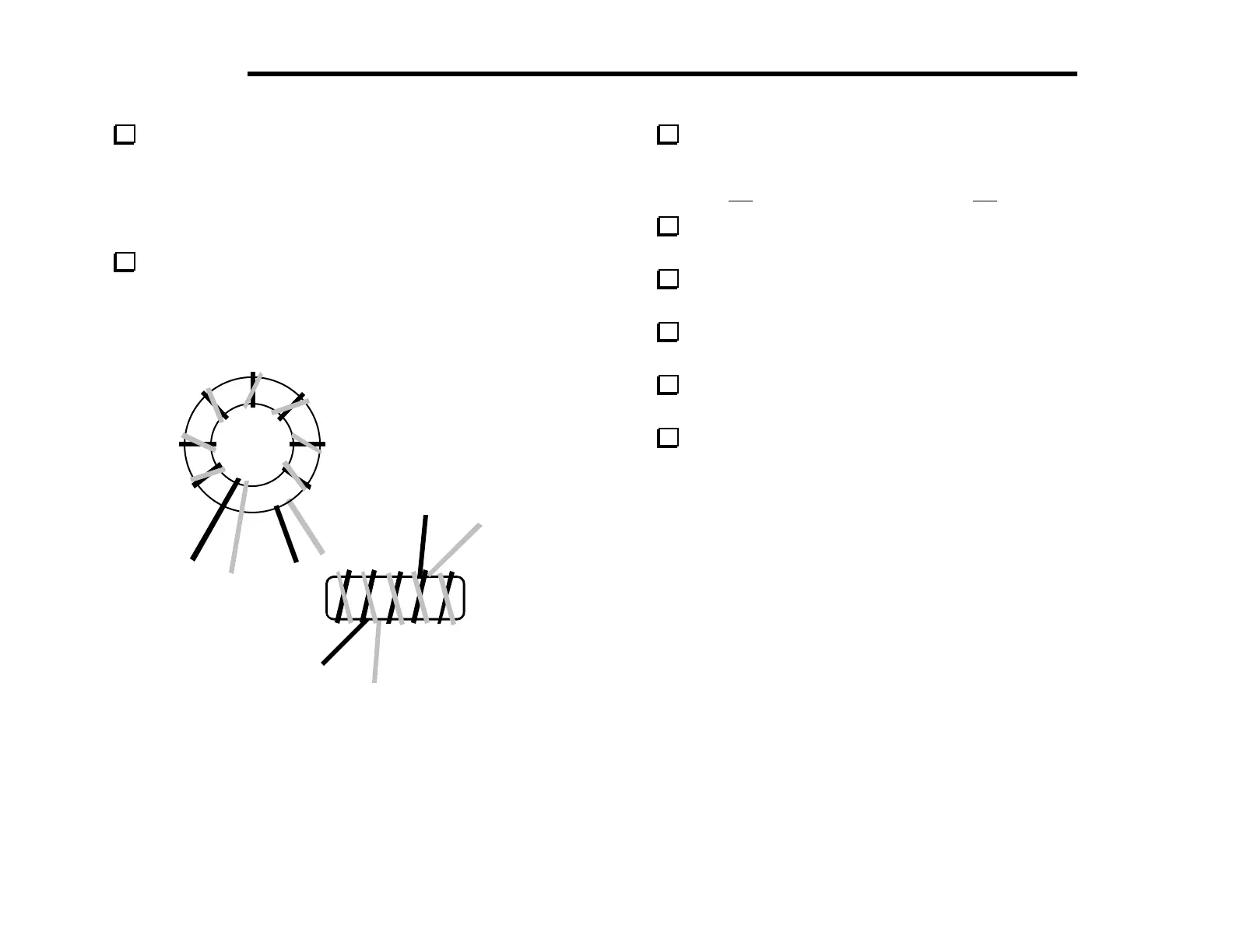
Transformer T6 is mounted vertically, near the middle of the
board. It uses a different winding technique where the wires for the
two windings are twisted together before winding ("bi-filar"). Cut
two 12" (30 cm) lengths of enamel wire, one red and one green.
Twist them together over their entire length. The wires should
cross over each other about once every 1/2" or 12 mm.
Wind the twisted wires onto a 3/8" (9.5 mm) ferrite core
(FT37-43), using exactly 10 turns. Use the same method you used
when winding non-twisted wires, covering about 85% of the core.
Figure 6-19 shows how the winding should look from two views
(your turns count will be 10 rather than 8 as in the drawing).
3
RED
2
GRN
1
RED
4
(GRN)
(a)
(b)
Figure 6-19
Clip and untwist the ends of the red/green pairs so that the
leads of the transformer look like those in Figure 6-19 (b). The pin
numbers shown match the component outline, with the red wires
numbered 1-3 and the green wires numbered 2-4
.
Strip and tin all four wires. Be careful not to strip the leads so
close to the core that the red/green wire pairs might short together.
Install T6 vertically, with the wires inserted as indicated in
Figure 6-19 (b). Pull the leads taut on the bottom, then solder.
Sort the slug-tuned shielded inductors into two groups: 1 µH
("T1050", quantity 4) and 4.7 µH ("T1005", quantity 8).
Install 4.7 µH inductors at L30 and L34 ("T1005"). Press
these inductors down as far as they’ll go before soldering.
Install the components listed below, starting with C39 in the
back left corner (near the key jack).
__ C39, .001 (102) __ C4, 820 (821)
__ C5, 100 (101) __ C9, .001 (102)
__ C7, 100 (101)
__ C8, 820 (821) __ C108, .01 (103)
__ W6 (option bypass jumper) __ D1, 1N4007
__ R38, 1 k (BRN-BLK-RED) __ D2, 1N4007
__ RFC1, 100 µH (BRN-BLK-BRN)
__ C107, .01 (103) __ C109, .01 (103)
__ C110, .01 (103) __ D3, 1N4007
__ D5, 1N4007 __ D4, 1N4007
__ R37, 100 k (BRN-BLK-YEL) __ R39, 1 k (BRN-BLK-RED)
__ C113, .01 (103) __ C114, .01 (103)
__ W1 (option bypass jumper)