ELECRAFT 55
i
The BFO toroid, L33, is supplied pre-wound due to
the large number of turns and very small gauge wire
required. When handling L33, be very careful not to
damage the leads.
Locate the rubber stem bumper. Clip off about one-half of the
tip of the stem using diagonal cutters.
L33 is located on the bottom of the board, near the front
center. Place the rubber stem bumper directly on top of L33's
component outline. Flush-trim the leads of all parts under or
near L33 so the stem bumper can sit flat on the PC board.
Locate the pre-wound BFO inductor, L33 (41 µH, 5%). It may
be supplied in a small envelope or bag labeled "L33".
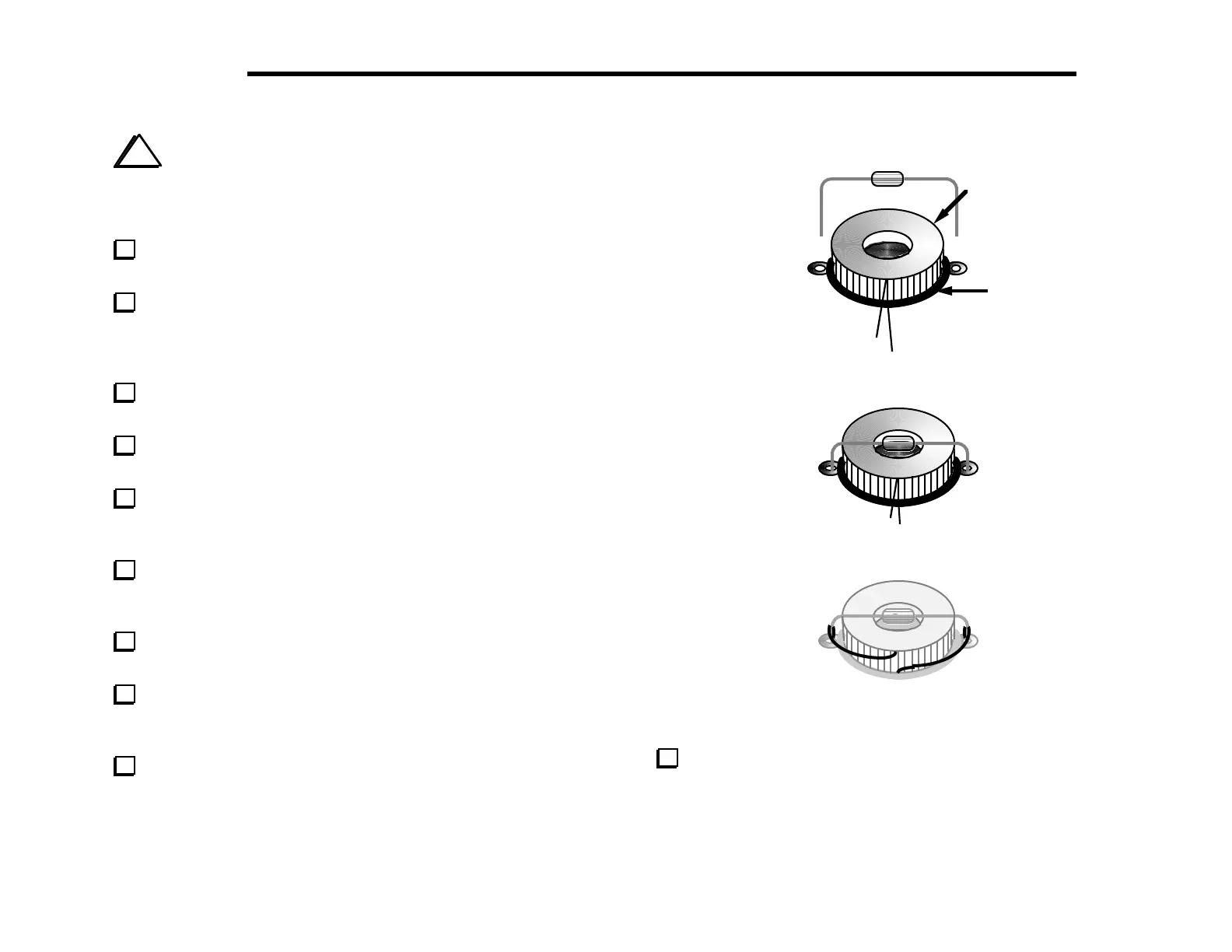
Press L33 down onto the stem bumper as far as it will go.
Position L33 and the stem bumper as shown in Figure 6-20.
Locate resistor R116 (1/8th watt, 5.1 megohm, green-brown-
green). Bend the leads of R116 down at 90-degree angles to match
the spacing of L33's pads (Figure 6-20).
Insert R116's leads into L33's pads, then press the resistor
down directly on top of L33. The resistor's body should be partially
recessed into the "well" left in the center of the toroid.
Use the leads of R116 to hold L33 firmly to the board (Figure
6-21), bending them outward on the top side. Solder R116.
Solder L33's leads to the leads of the resistor points as shown
in Figure 6-22. Keep L33's leads as short as possible, and away from
any nearby component pads.
Trim off the excess portion of L33's leads. Note: Trimming
fine wire may be difficult with worn or poor-quality diagonal
cutters. Be careful not to stress L33's leads in the process. Use a
magnifying glass if necessary.
L33
Stem Bumper
R116
Leads
Figure 6-20
Figure 6-21
Figure 6-22
To ensure that R116 cannot short to the bottom cover, attach
a thin self-adhesive insulator to the bottom cover in the area
directly beneath L33. Electrical or other types of tape may be used.