56 ELECRAFT
Visual Inspection
Examine the bottom (solder side) of the RF board carefully for
unsoldered pins, solder bridges, or cold solder joints. Since this is a
large board, you should break the examination up into three parts:
__ perimeter of the board __ front half __ back half
Examine the top (component side) of the RF board for
unsoldered pins, solder bridges, or cold solder joints. This step is
necessary because some components are installed on the bottom of
the board.
Make sure switch S1 on the RF board is in the OFF position.
(Plunger OUT is OFF.)
Resistance Checks
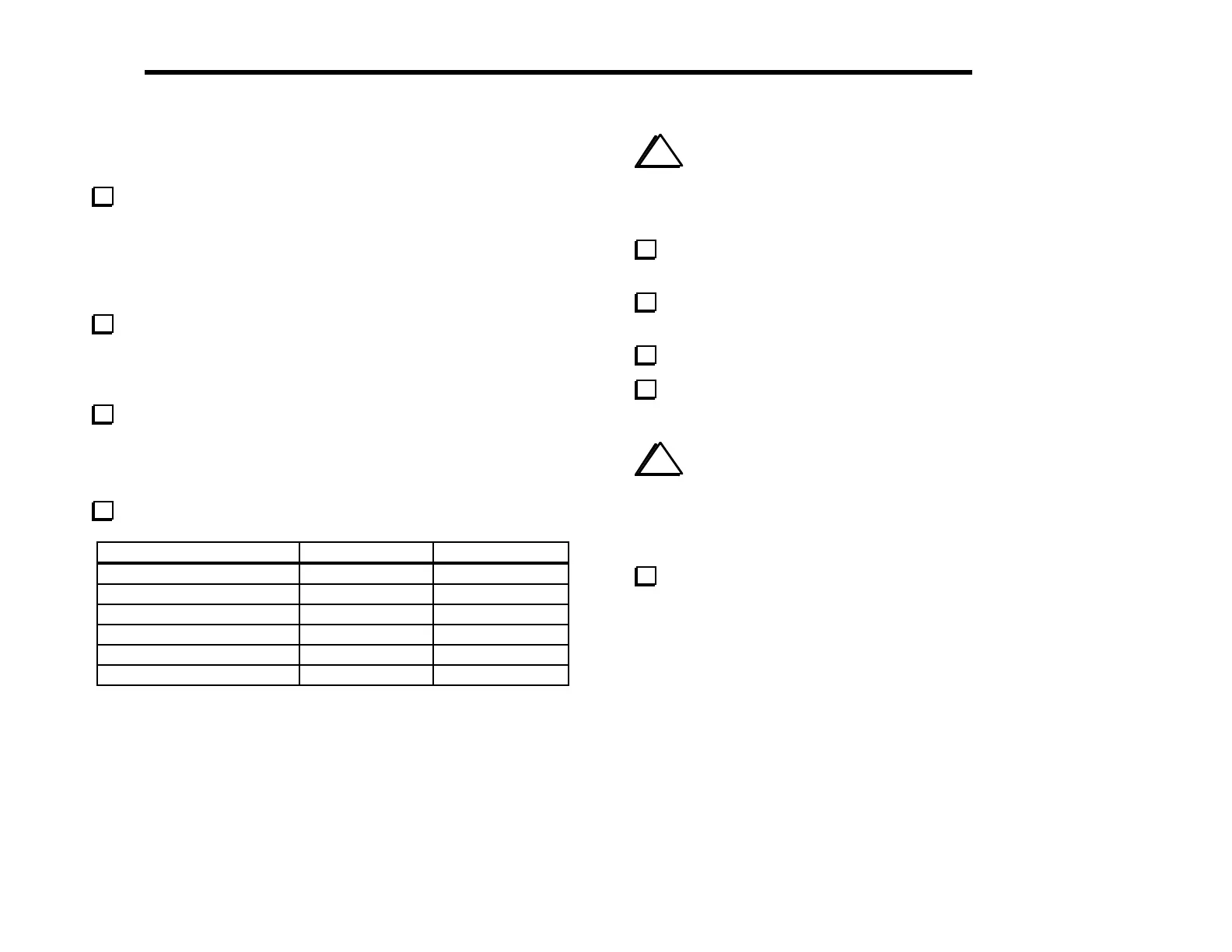
Perform the following resistance checks:
Test Point Signal Name Res.
to GND
R115, ri
ht end
near S1
12V IN > 500 ohms
U6 pin 8 8B > 100 ohms
U4 pin 16 5B > 1 k
U11 pin 8 8A > 250 ohms
U10 pin 8 8 T > 500 ohms
U12 pin 1 8R > 500 ohms
i
It is very important to re-assemble the chassis as described
below before attempting the alignment steps in the next section. If
you don’t put the chassis together, some alignment results will not
be accurate.
Install the two side panels and secure with two chassis screws
each.
Plug in the front panel assembly. Secure the front panel with
four chassis screws.
Plug in the Control board.
Secure the front panel and Control boards together using two
chassis screws.
i
Before installing the bottom cover in the following step,
verify that all components on the bottom of the RF board have an
installed height of 1/4" (6 mm) or less. Capacitors that stand above
this height must be bent downward at an angle to prevent them
from hitting the bottom cover.
Install the bottom cover and secure it temporarily using six
chassis screws.