64 ELECRAFT
i
TO-220 package transistors Q6, 7, and 8 look identical, but
Q6 is different. Locate the two 2SC1969’s (labeled "C1969"), Q7
and Q8, and set them to one side. The 2SC2166 transistor, Q6
("C2166"), will be installed first.
Attach a self-adhesive thermal pad to the PC board on top of
the component outline for Q6. The hole in the thermal pad must
be aligned precisely with Q6's mounting hole on the board.
Prepare the leads of Q6 as you did with the voltage regulators
on the Control board (Figure 4-4, page 16), using gradual bends to
avoid lead breakage. Insert Q6 as shown by its component outline.
Secure Q6 to the board using a 4-40 x 3/8" (9.5 mm) screw, #4
lock washer and 4-40 nut. The screw should be inserted from the
bottom side of the RF board; the washer and nut go on the top.
Verify that the body of Q6 is not touching the leads of any
adjacent components, then solder.
Wind and install each of the low-pass filter inductors listed
below, starting at the back-right with L16 and L17 (80 meters).
Wind each of the toroids using the core type and number of turns
indicated (use red enamel wire). Review the toroid winding
instructions and illustrations for RFC14 (Page 50).
__ L16 T44-2 (red), 21 turns 19" (48 cm)
__ L17 T44-2 (red), 21 turns 19" (48 cm)
__ L18 T44-2 (red), 9 turns 10" (25 cm)
__ L19 T44-2 (red), 8 turns 9" (23 cm)
__ L20 T44-2 (red), 7 turns 8" (18 cm)
Note: The black cores below are all of the powdered-iron (ceramic)
type, not ferrite. If necessary you can identify them by measuring
their diameter, which is 0.44" (11 mm), not 3/8" (9.5 mm).
__ L21 T44-10 (black), 9 turns 10" (25 cm)
__ L22 T44-10 (black), 8 turns 9" (23 cm)
__ L23 T44-10 (black), 11 turns 11" (28 cm)
__ L24 T44-10 (black), 10 turns 10" (25 cm)
i
It is very important to wind and install toroidal
transformers T1 through T4 exactly as described in the following
steps. Remember that transformer windings are identified by
numbered pairs of leads, which correspond to the PC board and
schematic.
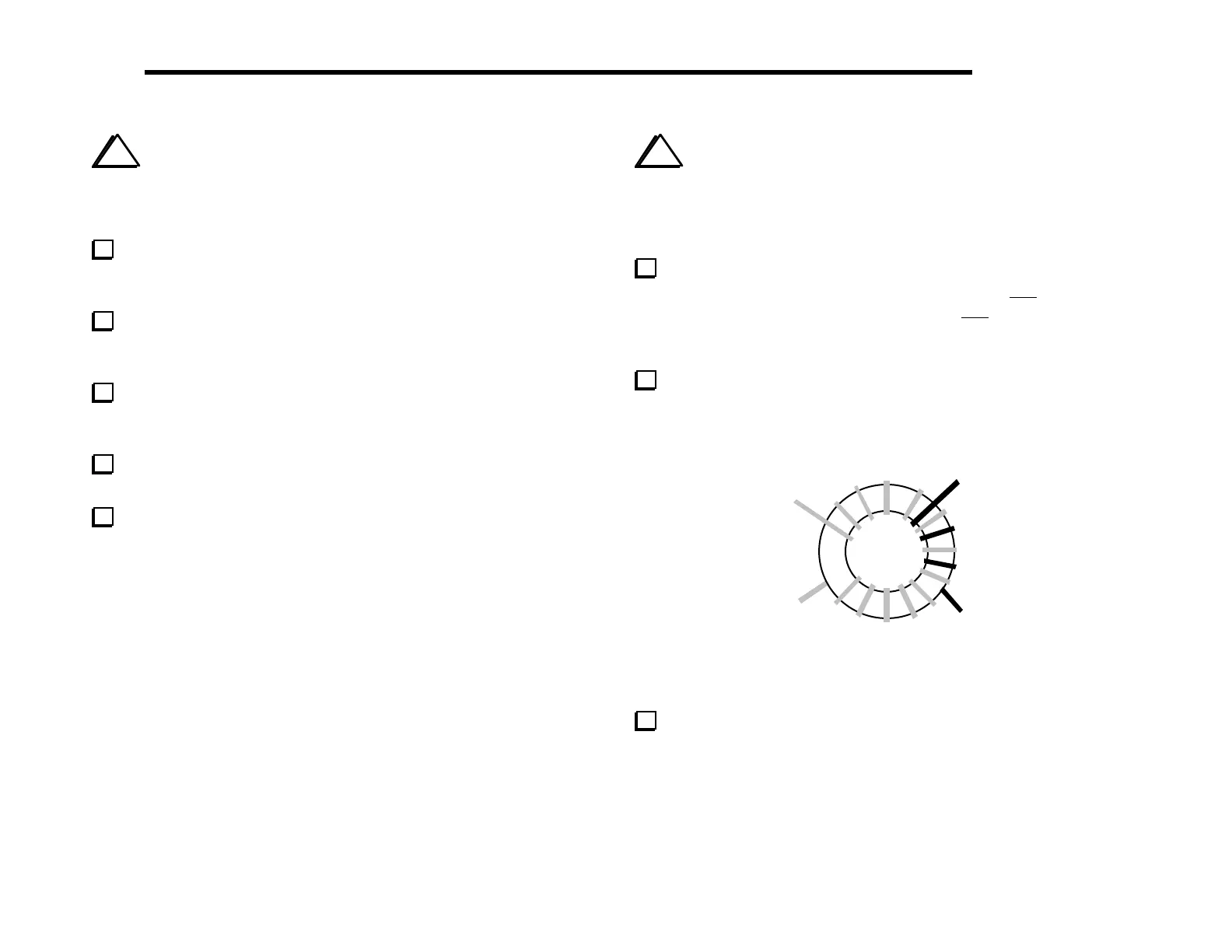
T1 is wound on an FT37-43 ferrite core (dark gray) and has
windings similar to those shown in Figure 6-25. The 1–2 winding is
9 turns of red enamel wire (10", 25 cm). The 3–4 winding is 3 turns
of green enamel wire (5", 13 cm). (The drawing shows more than 9
turns on the larger winding.)
Prepare T1’s leads as in Part II. Completely remove the
insulation to within about 1/8" (3 mm) of the core, then tin the
leads.
4
1
2
3
Figure 6-25
Install T1 horizontally near Q5, inserting the leads into the
matching numbered holes as indicated by the above illustration and
by the component outline.