ELECRAFT 65
T2 is wound on the same core type as T1 (FT37-43). Its
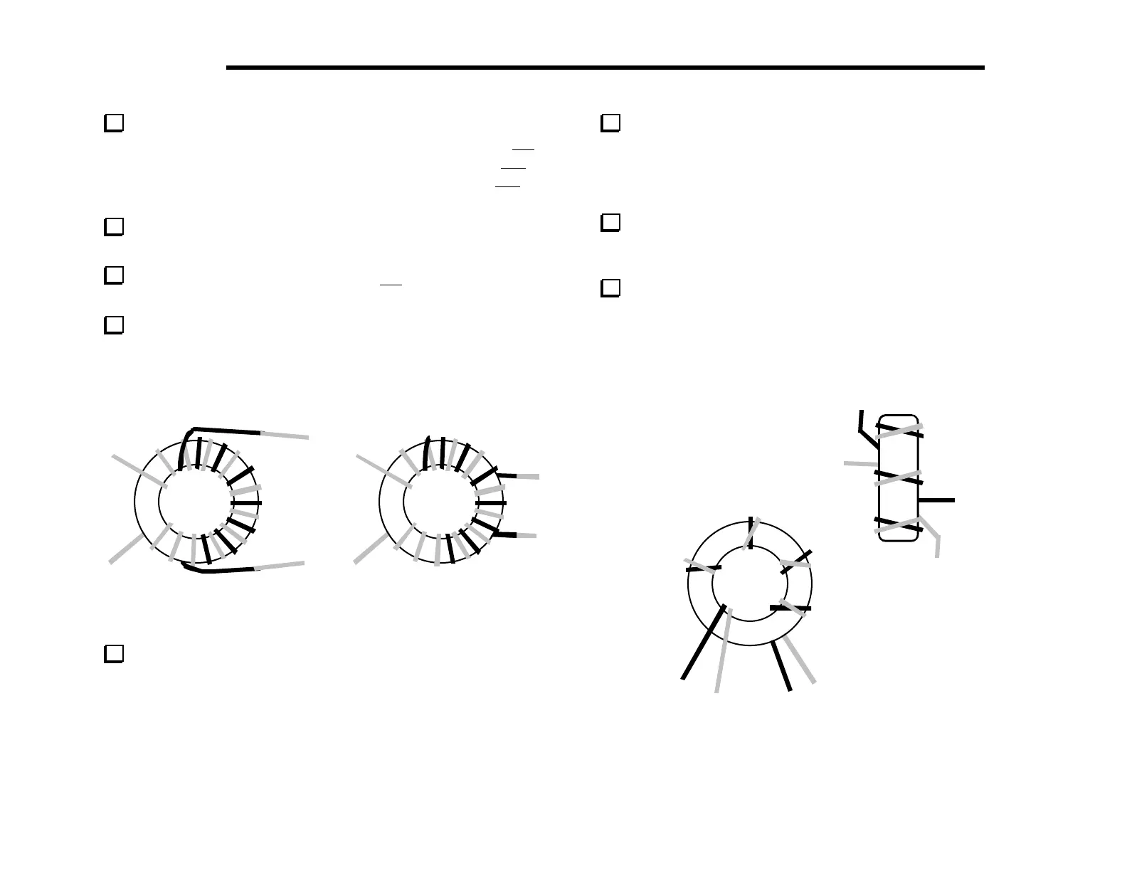
windings must be spaced as shown in Figure 6-26(a), with the 3-4
winding occupying about half the diameter of the core. T2’s 1–2
winding is 12 turns of red enamel wire (13", 33 cm), and its 3–4
winding is 8 turns of green (9", 23 cm).
Prepare T2’s leads, but leave an extra 1/2" of insulation on
leads 3 and 4 (green) as shown in Figure 6-26(a).
Fold the leads of T2's green winding (3-4) down and under the
core as shown in Figure 6-26(b).
Install T2 horizontally, just to the right of Q6. To ensure that
the leads do not contact any adjacent pads or components, T2
should be mounted so that it is elevated slightly above the board
(about 1/16" [1.5 mm]).
4
3
1
2
4
3
(a)
(b)
Figure 6-26
Transformer T3 is mounted vertically, to the right of T2. The
wires for the two windings must be twisted together before winding
(bi-filar). First, cut two 10" (25 cm) lengths of enamel wire, one
red, and one green. Then twist the wires together over their entire
length. The wires should cross each other once every 1/2" or 1 cm.
Wind the twisted wires onto a 1/2" (12.7 mm) dia. ferrite core
(FT50-43), using exactly 5 turns and covering about 85% of the
core. Figure 6-27 shows how the winding should look. The leads of
T3 are labeled with letters A through D on the PC board to avoid
confusing them with the numbered leads of T2 and T4.
Separate T3’s leads as shown in Figure 6-27. Strip and tin the
leads, being careful not to let the red/green wire pairs short
together.
Install T3 vertically as shown by its component outline. T3
must be seated flat against the PC board, with its leads pulled tight
on the bottom side.
C
(RED)
B
GRN
D
RED
A
(GRN)
Figure 6-27