66 ELECRAFT
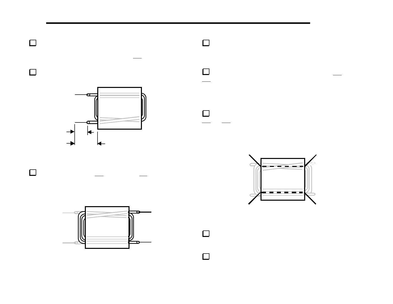
Locate the "binocular" (2-hole) ferrite core for T4. Wind 2
turns of green-insulated hookup wire (5", 13 cm) through the
core as shown in Figure 6-28. This forms the 1–2 winding. (Do not
use enamel-coated wire.)
Cut and strip the two leads using the lengths shown. Be careful
not to nick the wire.
2
1
1/2” (13mm)
7/8” (22mm)
Figure 6-28
Wind a 3-turn winding (3–4) on top of the 1-2 winding, but
with the wire starting and ending on the opposite side (Figure 6-29).
Use 7" (18 cm) of white-insulated hookup wire (not enamel-
coated wire). Prepare the leads in the same manner as above.
4
3
Figure 6-29
Before installing T4, verify that the screws holding the 2-D
fastener beneath it are tightened, and that #4 internal-tooth lock
washers were used. It is important that these screws not come loose
sometime after T4 has been installed.
Install T4 to the right of T3, inserting leads for the 1–2 and
3–4 windings into their matching numbered holes. T4 should rest
directly on top of the screws that secure the 2-D fastener beneath
it. T4 should also be parallel to the board, not tilted to one side.
Pull the leads taut on the bottom and bend them to hold the
transformer in place. Do not solder T4 yet.
Use two 2" (5 cm) lengths of bare hookup wire to form the
5–6 and 7–8
windings on T4 (Figure 6-30). (These are more
accurately described as links, each being just a single turn.) Route
the bare wires through the core first, then bend them down and
insert them into their numbered holes. Do not solder yet.
8
7
6
5
Figure 6-30
Adjust all of the windings of T4 as needed so that the
transformer is positioned directly above its component outline. Pull
the leads tight on the bottom, then solder.
Inspect all four transformers in the transmitter area closely,
on both top and bottom, for shorts or cold solder joints.