ELECRAFT 67
i
PA transistors Q7 and Q8 (2SC1969) must be installed on
the bottom of the PC board, with their metal tabs facing away from
the board, as explained in the following steps. Locate the
component outlines on the bottom of the board before proceeding.
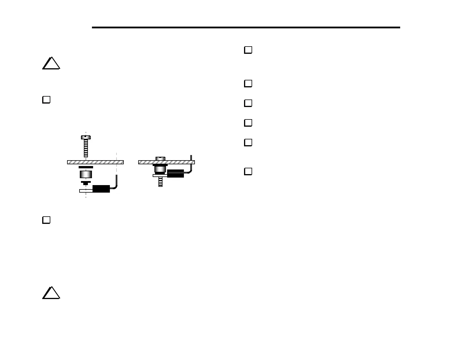
Prepare the leads of Q7 as shown in Figure 6-31. Bend the
leads upward, away from the tab--the opposite of the way you bent
the leads of Q6. Form the leads using the shaft of a small
screwdriver to create gradual bends. Do not install Q7 yet.
Figure 6-31
Insert a 4-40 x 1/2" (12.7 mm) screw through the PC board
hole for Q7’s tab (see Figure 6-31). Then slip the hardware listed
below onto this mounting screw from the bottom side. (The
shoulder washer can be found with the MISCELLANEOUS
components.)
__ #4 fibre washer (black)
__ 1/4" (6.4 mm) dia., 1/8" (3 mm) long phenolic standoff (brown)
__ #4 nylon shoulder washer (black)
i
Do not use any hardware other than that supplied. The
height of the PA transistor assembly is critical for maintaining
good heat dissipation.
Place Q7 on the bottom of the board so that the leads are
inserted into the PC board as indicated by Q7’s component outline.
The mounting screw and hardware should appear as shown in Figure
6-31. Do not solder yet.
Make sure the smaller part of the shoulder washer is visible
through the hole in Q7’s metal tab.
Secure Q7 and its hardware temporarily using a 4-40 nut and
#4 lock washer. Tighten the nut only finger-tight.
Once Q7 and its hardware appears to be parallel to the PC
board as shown in Figure 6-31, solder Q7 on the top of the board.
Repeat the steps above for the other PA transistor, Q8.
Uninstalled Components
Check off the components in the list below, verifying that
they are not yet installed. All of these components are on the top
side of the board. Note: Most of these components are provided
with option kits, as indicated in the list. Some of the connectors
can be pre-installed, as will be explained on the next page.
__ J14 (near antenna jack); supplied with K160RX
__ C13 and __ C14 (in 160 m band-pass filter); supplied with K160RX
__ C75 (synthesizer area); supplied with K160RX
__ J15 (3-pin connector in 40 m band-pass filter); supplied with K60XV
__ J13 (transverter conn., near 40 m band-pass filter); supplied with K60XV
__ D19 and D20 (synthesizer area); supplied with K60XV
__ P6 (near DC input jack); supplied with KAT2 or KPA100
__ P3 (near crystal filter); supplied with KBT2 or KPA100
__ J9, __ J10, and J11 (near crystal filter); supplied with KSB2
__ J12 (near crystal filter); supplied with KNB2
__ J5 (near BFO crystals); reserved for future use