70 ELECRAFT
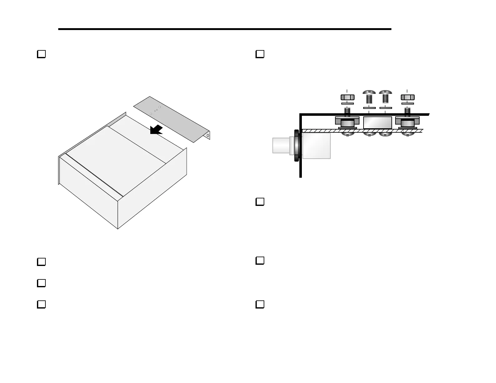
Keeping the K2 on its left side, slip the heat sink over the
rear-panel connectors and into position (Figure 6-33). Figure 6-34
shows how the heat sink and associated hardware appear in cross-
section.
Heat
Sink
Figure 6-33
Make sure that the four small holes in the heat sink line up
with Q7/Q8 and the 2-D block between them.
Press the Q7/Q8 mounting screws all the way back in so that
they protrude from the heat sink.
Use two chassis screws and two #4 lock washers to secure the
heat sink firmly to the 2-D fastener.
Secure Q7 and Q8 on the bottom of the heat sink using 4-40
nuts and #4 lock washers. Do not over-tighten the nuts, as this may
cause the thermal pads to scrape against the heat sink, possibly
causing a short to ground.
Figure 6-34
Using an ohmmeter on a low resistance scale, check for a
short from Q7 or Q8 collector to ground. (This test should also be
performed any time the heat sink is removed and re-installed.) If a
short is measured, remove the heat sink and investigate the cause.
The most likely reason for a short is mis-alignment of a shoulder
washer or thermal pad. If a thermal pad or shoulder washer is
damaged, it must be replaced.
There are four more #4 holes in the heat sink: two on the
bottom and two on the back panel. Use four chassis screws to secure
the heat sink to the side panels and RF board at these locations.
You may need to adjust the positions of the 2-D fasteners on the
side panels slightly.
Install the washers and finishing nuts that you removed earlier
from the antenna and key jacks. (The antenna jack hardware is
shown installed in Figure 6-34.)