ELECRAFT 69
Install the two side panels and secure with two chassis screws
each as you did in Part I and Part II.
Plug in the front panel assembly and make sure the connectors
are completely mated. Secure the front panel with four chassis
screws.
Verify that all components on the bottom of the RF board
have an installed height of 1/4" (6 mm) or less. Capacitors that
stand above this height must be bent downward so that they won’t
hit the bottom cover or heat sink.
Install the bottom cover and secure it using six chassis screws.
Plug in the Control board. Make sure that all three connectors
are completely mated.
Secure the front panel and Control boards together using two
chassis screws.
Locate the heat sink panel. Remove any masking tape,
including the large piece that covers several holes.
Attach two round rubber feet to the heat sink using 4-40 x
7/16" (11 mm) screws, #4 lock washers, and 4-40 nuts. The screws
are standard steel/zinc-plated, not black anodized. The nuts go on
the inside surface of the heatsink. (The rubber feet can be found
with the MISCELLANEOUS items.)
Remove the finishing nuts and washers from the shafts of the
antenna and key jacks. They will be re-installed later.
Turn the K2 up on its left side. This will keep the PA
transistor screws from slipping out during the following steps.
Remove the 4-40 nuts and #4 lock washers from the mounting
screws for Q7 and Q8, but do not pull the screws out. (If you pull
these screws out, the associated hardware will fall off and will have
to be re-installed.)
i
In the next step you'll install thermal insulation pads on
the power amplifier transistors, Q7 and Q8. These pads must be
positioned correctly to keep the collectors of the transistors from
shorting to ground. Proper positioning is also required to guarantee
good heat conduction.
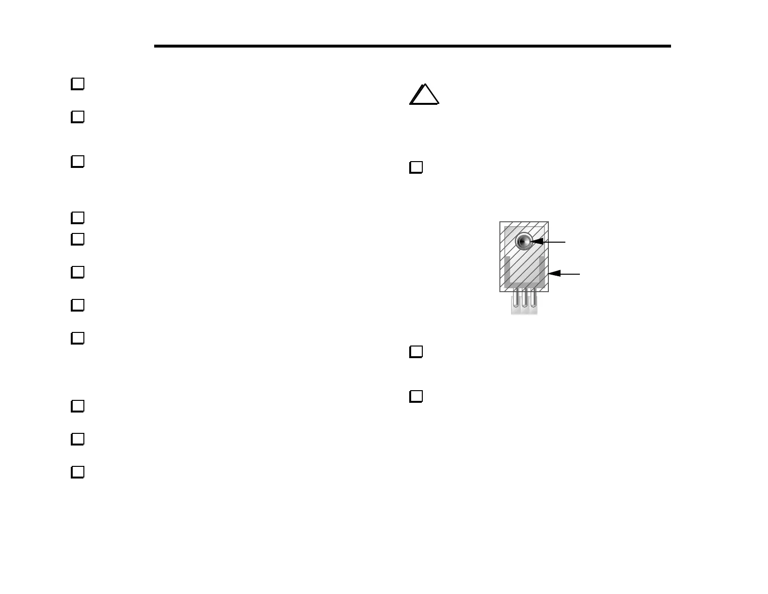
Place self-adhesive thermal pads on top of Q7 and Q8 as
shown in Figure 6-32, with the hole in the pad centered over the
hole in the transistor tab. The adhesive side must be in contact with
the transistor.
4-40 screw
Thermal
Pad
Figure 6-32
Back out the mounting screws for Q7 and Q8 until the ends of
the screws protrude only slightly from the transistor tabs. Keep the
K2 on its left side so the screws don’t slip out further.
Make sure that the thermal pads on Q7 and Q8 are centered,
and that you can see the shoulder washers inside the tab holes. If
the shoulder washers have come out of the tab holes, re-align the
PA transistor hardware as needed.