ELECRAFT 7
3. Preparation for Assembly
Overview of the Kit
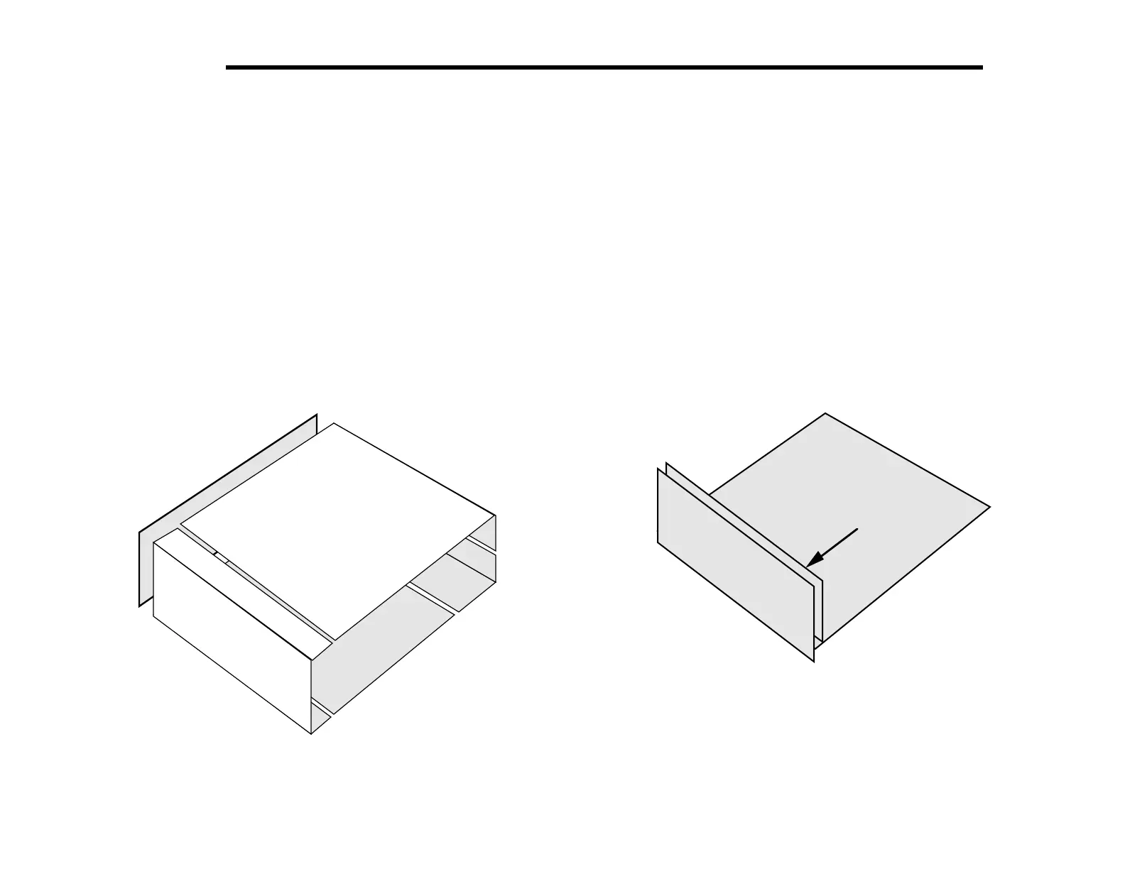
The K2 uses modular construction, both physically and electrically.
This concept extends to the chassis (Figure 3-1). Any chassis
element can be removed during assembly or troubleshooting. (Also
see photos in Appendix D.) If the KPA100 is installed, it takes the
place of the original top cover.
Top Cover
Front
Panel
Side
Panel
Bottom
Cover
Heat
Sink
(Right side panel
not shown)
Figure 3-1
As shown in Figure 3-2, there are three printed circuit boards
(PCBs) in the basic K2 kit: the Front Panel board, Control Board,
and RF board. Option modules plug into the RF or Control board,
but are not shown here.
RF
Front
Panel
Control
Figure 3-2