8 ELECRAFT
Board-to-board Connectors
The circuit boards in the K2 are interconnected using board-to-board connectors, which eliminates nearly all hand wiring. Gold-plated contacts
are used on these connectors for reliability and corrosion resistance.
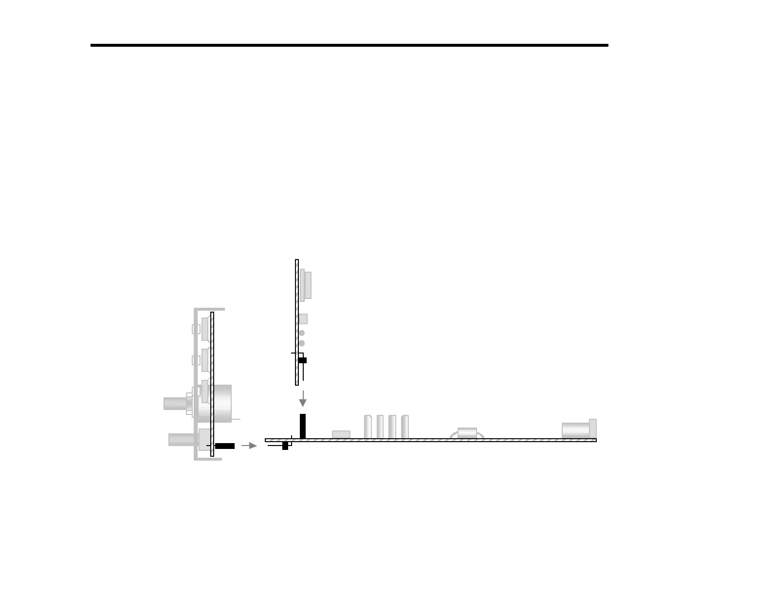
Figure 3-3 shows a side view of the PC boards and board-to-board connectors. As can be seen in the drawing, the Front Panel board has a
connector J1 which mates with right-angle connector P1 on the RF board. Similarly, right-angle connector P1 on the Control Board mates
with J6 on the RF board. (Not shown in this drawing are two additional right-angle connectors on the Control board, P2 and P3, which mate
with J7 and J8 on the RF board.)
These multi-pin connectors are very difficult to remove once soldered in place. Refer to Figure 3-3 during assembly to make
sure you have each connector placed correctly before soldering.
1
P1
J6
P1
ront Panel
F Board
Control Board
Figure 3-3