K3 KSYN3 Gain Modification Page 2 of 5
Removing the KSYN3 Board(s)
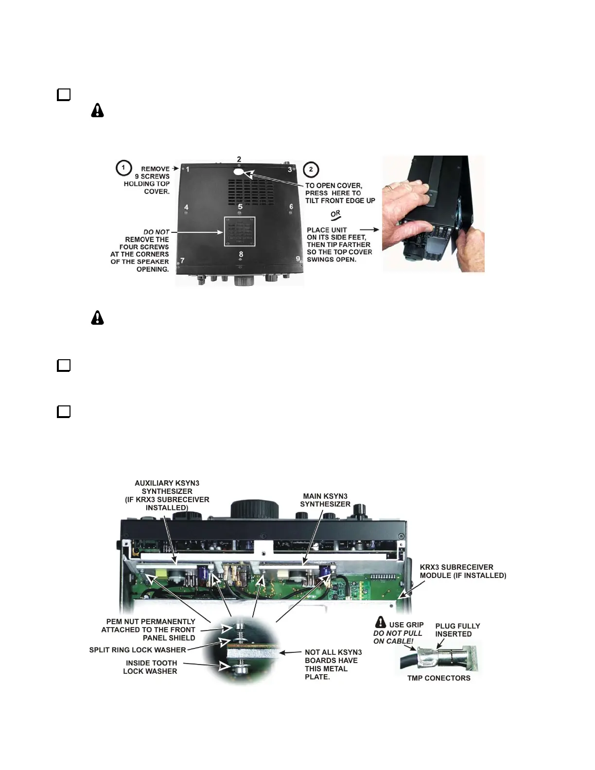
Remove the K3 top cover as shown in Figure 1.
Whenever you remove screws from a panel, if one screw seems too tight to loosen
without damaging it, first loosen the other screws then try again. Sometimes one screw
binds in its hole when the other screws are tightened
.
Figure 1. Removing the Top Cover.
CAUTION:
Touch an unpainted metal ground or wear a grounded wrist strap
before touching components or circuit boards inside the K3.
If you are modifying the main KSYN3 board (see Figure 2) and the K144XV 2-meter option is installed,
remove the K144XV module. Remove the three screws securing it to the right side panel. You can move it out
of the way while removing the synthesizer or you can unplug the connectors and set it aside.
Remove the KSYN3 board(s) to be modified (see Figure 2). If the optional K144XV 2-meter module is
installed, remove it to gain access to the mounting screws for the main KSYN3 board. Each board plugs into the
RF board on bottom of the K3 and is held in place with two screws at the top. Loosen the screws and tip the
boards to remove the split lock washers. Unplug the TMP coaxial cables as you lift each board out. The TMP
connectors are held by friction. Pull only on the metal ears of the TMP plug. Do not pull on the coaxial cables.
Figure 2. Removing the KSYN3 Boards.