EasyManua.ls Logo

Electro-Harmonix MICRO Q-TRON User Manual

Electro-Harmonix MICRO Q-TRON
2 pages
To Next Page IconTo Next Page
Page #1 background imageLoading...
Page #1 background image
FCC COMPLIANCE
Note:
This equipment has been tested and found to comply with the limits for a Class
B digital device, pursuant to part 15 of the FCC Rules. These limits are designed to
provide reasonable protection against harmful interference in a residential
installation. This equipment generates, uses and can radiate radio frequency energy
and, if not installed and used in accordance with the instructions, may cause harmful
interference to radio communications. However, there is no guarantee that
interference will not occur in a particular installation. If this equipment does cause
harmful interference to radio or television reception, which can be determined by
turning the equipment off and on, the user is encouraged to try to correct the
interference by one or more of the following measures:
Reorient or relocate the receiving antenna.
Increase the separation between the equipment and receiver.
Connect the equipment into an outlet on a circuit different from that to
which the receiver is connected.
Consult the dealer or an experienced radio/TV technician for help.
Modifications not expressly approved by the manufacturer could void the user's
authority to operate the equipment under FCC rules.
MICRO Q-TRON
Envelope Controlled Filter
Congratulations on your purchase of the Micro Q-Tron envelope controlled filter! The
Micro Q-Tron is identical to our Mini Q-Tron but in a compact pedal. The envelope
controlled filter is a unique type of sound modifier in which the user’s playing style
controls the effect. The volume of the input signal (also called the envelope) controls
the cutoff frequency or center frequency of a swept filter. As your instrument’s
volume increases or decreases, so does the pitch of the filter.
-CONTROLS-
DRIVE CONTROL – This is the filter sweep sensitivity control. Turning the DRIVE
control clockwise will cause the filter to react more to your playing. The more you
turn up the DRIVE control, the higher in frequency the filter will jump when you play
a note. When first plugging into the Micro Q-Tron, start with this control at 12
o’clock.
Q CONTROL – Determines the peak bandwidth of the filter. As the Q control is
turned clockwise, the filter will sound increasingly narrow with a more obvious peak,
making the effect more dramatic. Start with Q set to about 2 o’clock.
MODE ROTARY SWITCH (LP BP HP) – Determines what frequency range the filter
will pass. Emphasizes lows in LP mode (Low Pass), midrange in BP mode (Band Pass)
and highs in HP mode (High Pass).
STATUS LED – When the LED is lit, the Micro Q-Tron is in effect mode. When the
LED is off, the Micro Q-Tron is True Bypass mode.
FOOTSWITCH – Toggles the Micro Q-Tron between effect and True Bypass modes.
CONNECTIONS – Connect your instrument to the INPUT Jack. Connect your amplifier
to the AMP Jack.
Question and Answer IconNeed help?

Do you have a question about the Electro-Harmonix MICRO Q-TRON and is the answer not in the manual?

Electro-Harmonix MICRO Q-TRON Specifications

General IconGeneral
TypeEnvelope Filter
Dimensions4.5” x 4.5” x 2.25”
Weight1.25 lbs.
Power9VDC
Input Impedance1M Ohm
Output Impedance1 kΩ
SwitchTrue Bypass
BypassTrue Bypass
Power Supply9V battery or optional 9V AC adapter
Mode SwitchLP, BP, HP

Summary

FCC Compliance Regulations

HXQ Micro Q-Tron Product Overview

Micro Q-Tron Controls

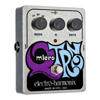
Details the function of the DRIVE, Q, MODE, STATUS LED, FOOTSWITCH, and CONNECTIONS controls.

Drive Control Function

Adjusts filter sweep sensitivity. Higher settings react more to playing dynamics.

Q Control Function

Determines filter bandwidth. Higher settings create a narrower, more obvious peak.

Mode Rotary Switch

Selects frequency range: Low Pass (LP), Band Pass (BP), or High Pass (HP).

Status LED Indicator

Indicates when the Micro Q-Tron is active (lit) or in True Bypass (off).

Footswitch Operation

Toggles the pedal between effect mode and True Bypass modes.

Input and Output Connections

Connects instrument to INPUT and amplifier to AMP jack for signal routing.

Powering and Battery

Power Source Activation

Power is activated by plugging into the Input jack. Remove cable when not in use.

Battery Replacement

Instructions for changing the 9V battery, involving removing bottom screws.

Playing Techniques and Effects

Playing Dynamics Influence

Playing dynamics (attack, volume) control the filter's reaction and effect intensity.

Filter Response to Notes

Notes trigger filter sweeps; louder notes result in higher frequency jumps.

Warranty and Customer Service

Warranty Registration and Terms

Register online or return card. One-year warranty for defects in materials/workmanship.

Returning Unit for Service

Contact EHX for RA#, provide problem description, contact info, and receipt copy.

Customer Service Contact Information

Provides contact details for EHX Customer Service in the US/Canada and Europe.

Related product manuals