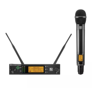
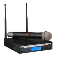
UHF Wireless RE3-RX r eceiver | en 23
-Voice Installation manual 2021.06 | 03 | F.01U.362.808
remote extension antenna. This jack supplies 12 volts DC booster
feed to power in-line RF amplifiers or active antennas when
antenna power is set to on (factory default). The RE3 diversity
receiver requires connecting antennas to both antenna jacks.
13
AF output jack
(unbalanced
audio)
¼” audio output jack (¼” TS). Using a standard unbalanced
instrument cable with ¼” plugs, connect this to the unbalanced
line input jack on a mixer, powered loudspeaker, or instrument
amplifier.
14
AF output jack
(balanced audio)
XLR audio output jack (XLRM). Using a standard balanced
microphone cable, connect this to the balanced microphone input
jack (mic level) on a mixer, powered loudspeaker, or signal
processor.
15 Antenna B jack
BNC RF jack to attach either a supplied half-wave whip antenna,
or antenna extension coax cable connected to a front-mounted or
remote extension antenna. This jack also supplies 12 volts DC
booster feed to power in-line RF amplifiers or active antennas
when antenna power is set to on (factory default). The RE3
diversity receiver requires connecting antennas to both antenna
jacks.
16 DC power jack
Connection point for receiver’s external power supply. This is
where a DC distribution lead connects when using the optional
AASP antenna splitter.
 Loading...