29
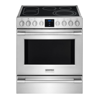
5.1.4. GAS PRESSURE REGULATOR
• A gas pressure regulator (supplied in a plastic bag with the
appliance)must be installed in an easily accessed posi-
tion ahead of the appliance.
The pressure regulator should preferably be fitted horizontally,
to ensure the right outlet pressure:
•“1” connection side gas from mains.
•“2” pressure regulator (3.3"x2.9"x2.7"/85x75x71mm);
•“3” connection side gas towards the appliance;
The arrow on the regulator (
) indicates the gas flow
direction.
AUSTRALIA: the gas pressure regulator supplied with
theappliance must be fitted to the appliance inlet. Adjust
thetest point pressure with one burner operating at maximum
setting as follow:
- 0.7 KPa for Natural gas
- 1.8 KPa for Propane gas
NB! These models are designed and certified for use with
natural or propane gas.
5.1.5. PRIMARY AIR CHECK
When the primary air is correctly adjusted, the flame does
not “float” with burner cold and there is no flareback with
burner hot.
5.1.6 CONVERSION TO ANOTHER TYPE OF GAS
Table B “technical data/gas nozzles” gives the type of nozzles
to be used when replacing those fitted by the manufacturer
(the number is stamped on the nozzle body). At the end of
the procedure, carry out the following check-list:
Check Ok
• burner nozzle/s change
• correct adjustment of primary air at burner/s
• pilot nozzle/s change
• minimum flame screw/s change
• correct adjustment of pilot/s if necessary
• correct adjustment of supply pressure (see
technical data/gas nozzles table)
• apply the sticker (supplied) with data of new gas
type used
5.1.6.1 MAIN BURNER NOZZLE REPLACEMENT (hob - fig. 3A)
• Lift and remove the main burner;
• Unscrew nozzle “B” and replace it with one suitable for
the type of gas according to that given in Table B.
• The nozzle diameter is given in hundredths of mm on the
nozzle body.
• Tighten down nozzle “B”.
5.1.6.2 MAIN BURNER NOZZLE REPLACEMENT (oven - fig.
3B-3C-3D-3E)
• Remove the oven floor.
• Remove protection shield “A” (fig. 3B).
• Loosen screw “B” and lift the retainer of burner “C” (fig. 3C).
• Loosen the screw of bushing “E” (fig. 3E).
• Pull out and remove burner “D” (fig. 3D).
• Replace nozzle “F” with one suitable for the type of gas,
according to that given in Table B.
• The nozzle diameter is given in hundredths of mm on the
nozzle body.
• Refit the burner and retainer, retighten screws “C” and “E”
and refit the oven floor.
5.1.6.3 PILOT BURNER NOZZLE REPLACEMENT (oven -
fig. 3B-3F)
• Remove the oven floor.
• Remove protection shield “A” (fig. 3B).
• Remove pilot burner protection cover “G”
• Unscrew nipple “H” and replace nozzle “L” with one suitable
for the type of gas (Table B, fig.3F).
• The nozzle identification number is given on nozzle body.
• Retighten nipple “H” and refit the protection and oven floor.
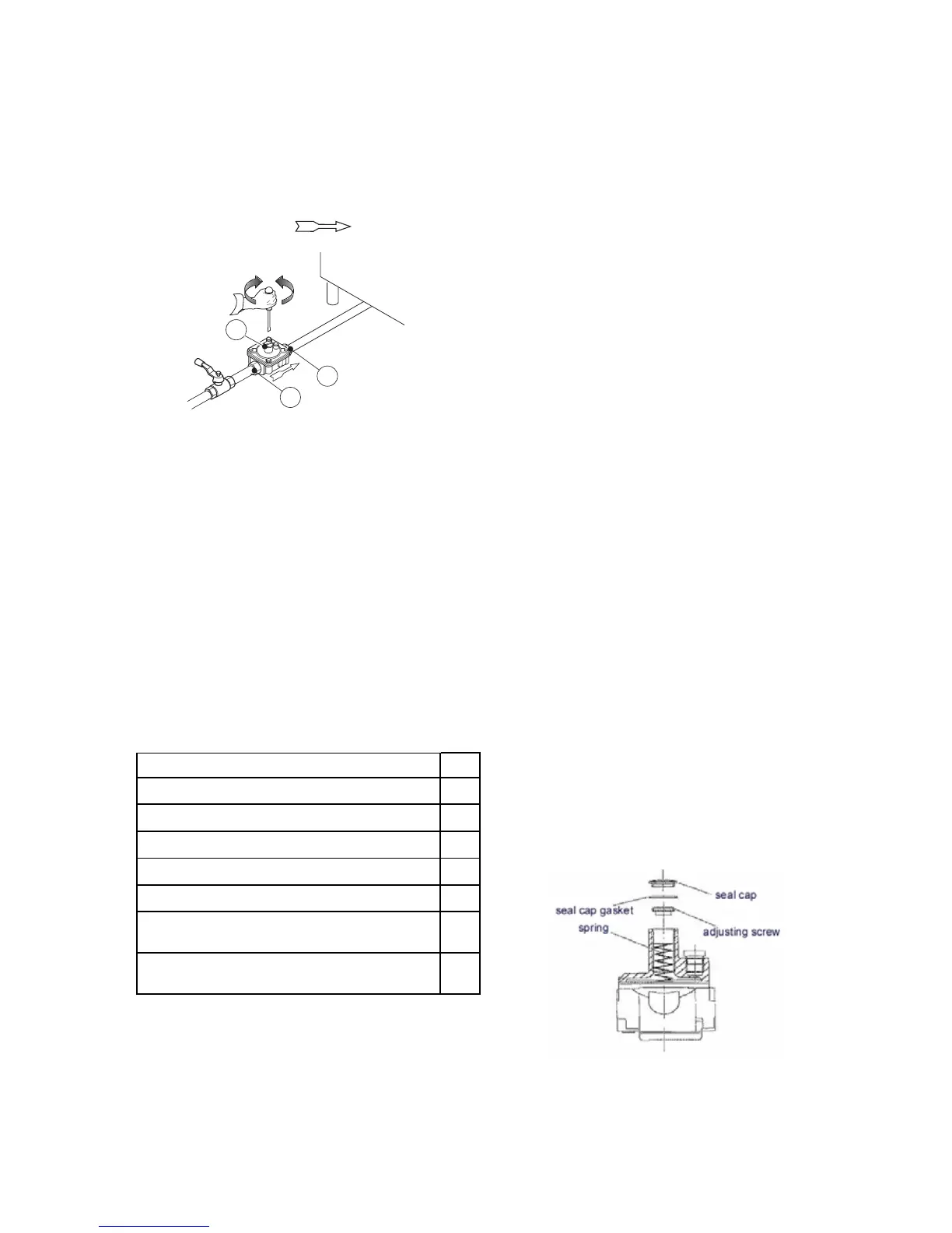
5.1.6.4 REPLACING THE ADJUSTMENT SPRING OF THE
PRESSURE REGULATOR
• Replace the spring of the pressure regulator with one
suitable for the gas pressure type given in table B (see
handbook Appendix) as follows:
- Remove the seal cap, seal cap gasket, adjusting screw
and the spring.
- Insert the new spring and replace the adjusting screw.
- Connect a pressure gauge to the appliance’s test point
pressure (fig. 2A/2B).
- Ignite the appliance’s burners so to have the maximum
gas consumption.
- Regulate the adjustment screw until the pressure gauge
shows the working pressure value (section 5.1.4 Gas
pressure regulator).
- Replace the seal cap and gasket and screw tightly closed.
- Remove the pressure gauge and close the test point
pressure.
- Prior to operation, test the gas pressure regulator for leaks.