7.
A.
B.
C.
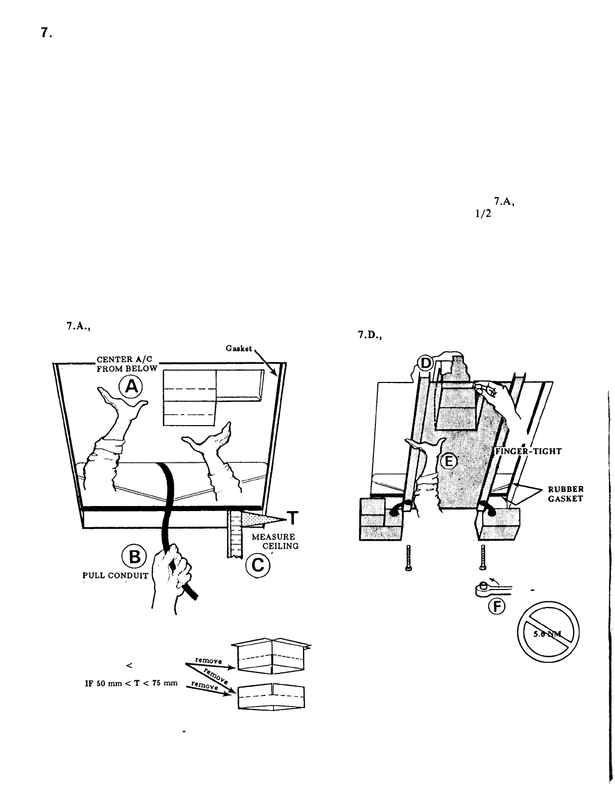
CEILING TEMPLATE
INSTALLATION
Reach through the roof opening and adjust
the air
conditioner until the gasket
is
centered on the opening. (FIG. 7.A)
Reach up into the return air opening and
pull the conduit power cable down for
later connection. (FIG. 7.B)
Measure the roof thickness:
1.
If the distance is 25 to 50 mm,
remove
the perforated tabs on the
upper discharge air duct and tabs on
the lower discharge air duct.
2.
If the distance is 50 to 75 mm,
remove
the perforated tabs on the
lower discharge air duct.
3.
If the distance is 75 to 110 mm, do
not
remove
any of the perforated
tabs. (FIG. 7.C)
FIG.
7.A.,
B.,
C.
Casket,
THICKNESS
THROUGH
IF 26 mm
<
T < 60 mm
IF50mm<T<75mm
D.
Take the ceiling template and slide the
lower discharge air duct over the outside
of the upper discharge air duct.
E.
Holding the ceiling template in place with
one hand, install the three 150 mm long
mounting bolts up through the ceiling
template and into the air conditioner with
other
hand,
until mounting
bolts
are
finger-tight. (FIG. 7.E)
F.
Evenly torque the three mounting bolts to
4.5 to 5 NM to secure the air conditioner
to the roof and insure a good water seal.
The rubber gasket (FIG. 7.A, B, C) should
compress to roughly
l/2
of its original 25
mm thickness. (FIG. 7.E)
CAUTION:
DO NOT
overtighten the mounting bolts as this
may damage the air conditioner base.
FIG.
7.D.,
E.
*
4.5
-
5.5
NM
IF 75 mm < T < 110 mm - INSTALL AS PACKAGED