8. CONNECTION OF POWER SUPPLY
TO AIR CONDITIONER (Fig. 8)
WARNING
Be sure power supply is OFF before connecting
power supply leads to the air conditioner.
A.
Route the power supply line, previously
installed to the roof opening,
into the
junction box on the ceiling template.
B.
Connect the power supply line to the air
conditioner at the terminal block provided
in the junction box. Connect red to red,
black to black and green to green or bare
copper wire, (P, P, and
h
respectively).
C.
Tighten the strain relief onto the power
supply line, to hold it firmly in place.
D.
Carefully push all excess wire back into
the junction box and install covers onto
the boxes with three blunt tipped screws
provided.
E.
Plug the electrical conduit hanging from
the bottom of the air conditioner into the
mating connector on
the switch box
located on the ceiling template.
FIG. 8
CEILING TEMPLATE
Rr
HEATING ASSEMBLY
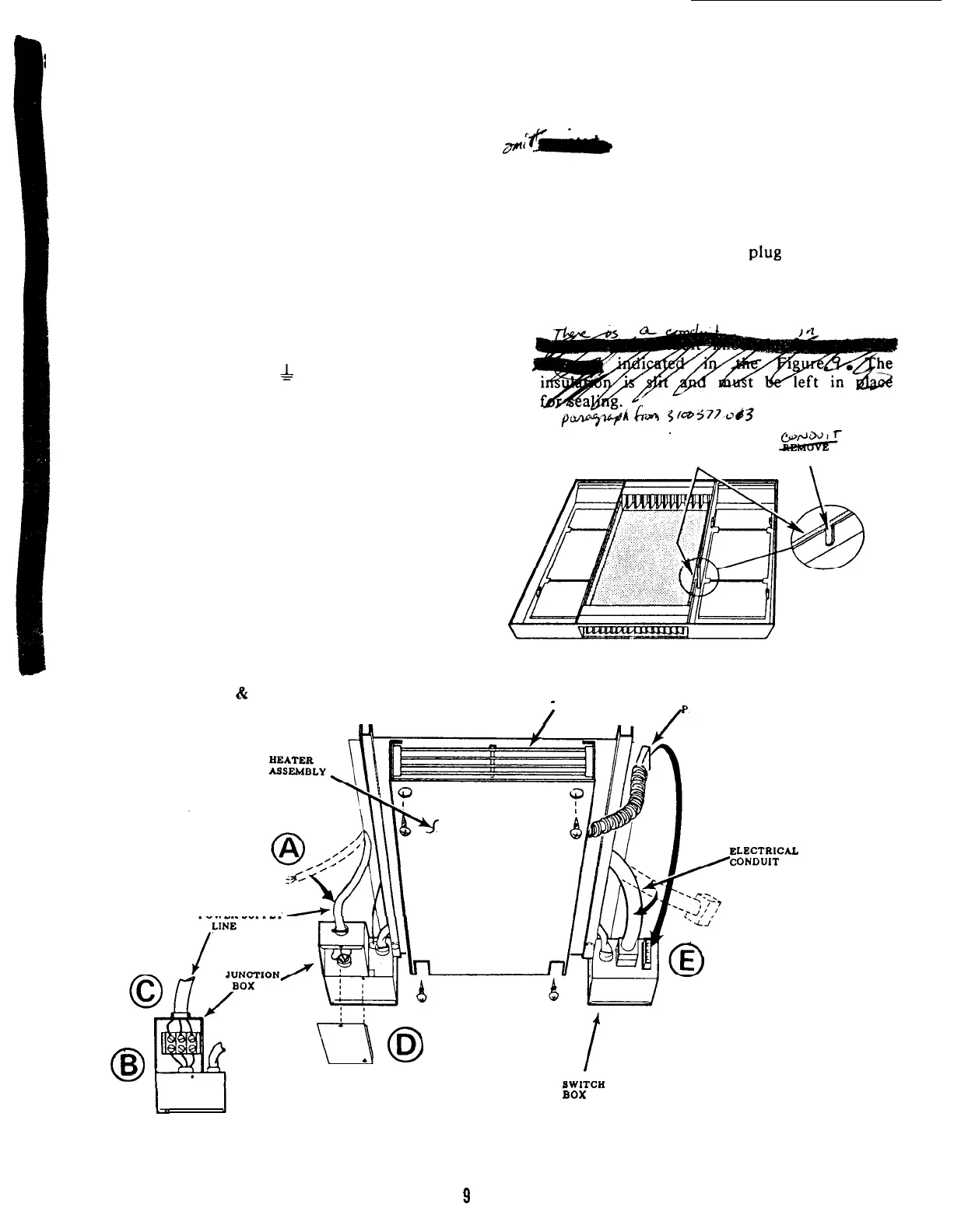
9. HEATER INSTALLATION (FIG. 8)
A.
Install the heat package to the ceiling
template
the
fl;F-
using four (4) pointed,
screws provided. The heater
element will
align below the discharge air
B.
C.
opening and the mounting holes will align
with the prepunched holes in the’ ceiling
template.
Push
the electrical
PlW
onto
the
receptacle at the back of the switch box.
Push excess conduit up into return air
opening.
FIG. 9
LEAVE
INSULATION
IN PLACE
KNOCKOUT
GRILL
-
THIS END ONLY
ELECTRICAL
/
LUG
LECTRICAL
ONDUIT
POWER SUPPLY
I
’
0
B
r-7
0
D
.
I..
BOX
BOTTOM VIEW
JUNCTION BOX
9