models67/68.E3andE10bothhaveaudible
alarms.P1doesnothaveanaudiblealarm.
24
Quick Reference Card
1. Plug in unit.
2. The display may show a SP or --, either is OK.
3. Install a jumper on J3.
4. Hold down warmer, colder,and light button until
display shows model numberand main board beeps.
5. Use warmer/colder to select new model number.
6. Press and release light key.
7. Wait for display to stop flashing.
8. Remove jumper from board.
9. Unplug unit and wait 5 seconds.
10. Plug unit back in.
* Note: Models 2275DWRWS cannot be programmed on the
same board as the other models.
Échelon Model Selection:
TRAHC ECNERE F ER YA L ER
Model
Part
Number
PIN 7
C_FAN
PIN 6
LIGHTS
PIN 5
PIN 4
H_H2O
PIN 3
C_PUMP
PIN 2
R_VALVE
PIN 1
BP_VALVE
Relay 1 Relay 2 Relay 3 Relay 4 Relay 5 Relay 6 Relay 7
thgiL57 / 16R5712
Compressor/
Fan
thgiL37 / 17R5112
Compressor/
Fan
thgiL47 / 27CW5112
Compressor/
Fan
1 thgiL07
64/78
RRWD5712
Com
pressor/
Fan
Pan Heat Mull Heat
CO2175F
Cond Fan
E FAN
Light Compressor
Hot Gas
Valve
DRAIN HEAT IM 1 IM 2
2175RF 65/79
Cond Fan
E FAN
Light Compressor
Hot Gas
Valve
DRAIN HEAT
CO2175DWR 66/80
Cond Fan
E FAN
Light Compressor
Hot Gas
Valve
MULL HEAT IM 1 IM 2
CLR2160 67/81 Cond Fan Compressor
Hot Gas
Valve/ Water
Valve
Circulation
Pump
CLRCO2175 68/82 Cond Fan Light Com
pressor
Hot Gas
Valve/Water
Valve
Circulation
Pump
Ref Valve
Ref Bypass
Valve
Compressor/
Fan
thgiL77136VEB5712
2275DWRWS 85186Cond Fan Bottom Light Compressor Top Light Bottom Valve Top Valve
61-2175R 120V
62-2175WC 120V
63-2175BEV 120V
64-CO2175F 120V
65-2175RF 120V
66-CO2175DWR 120V
67-CLR2160 120V
68-CLRCO2175 120V
70-2175DWR 120V
71-2115R 120V
72-2115WC 120V
73-2115R 220V
74-2115WC 220V
75-2175R 220V
76-2175WC 220V
77-2175BEV 220V
78-CO2175 220V
79-2175RF 220V
80-CO2175DWR 220V
81-CLR2160 220V
82-CLRCO2175 220V
85-2275DWRWS 120V*
86-2275DWRWS 220V*
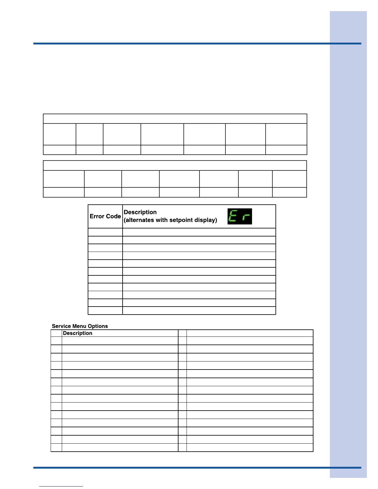
E1 Thermistor #1 open
E2 Thermistor #1 shorted
E3 Door #1 open longer than 20 minutes
E5 Thermistor #1 out of range (+10) for more than 12 hours
E6 Thermistor #1 out of range (-10) for more than 12 hours
E7 Thermistor #2 open or shorted
E8 Thermistor #3 open or shorted
E9 Thermistor #4 open or shorted
E10 Door #2 (drawer) open longer than 20 minutes
E11 EE Memory Error
P1 Pump circuit open due to high water level in ice bin
## Description
l a i t ne r e f f i d 1# r o t s imr eh t t su j dA51s t nemgeS DEL l l a t hg i L1
2 Thermistor #1 status (Temp, E1 or E2) 16 Adjust thermistor #2 offset
tesf fo 3# rotsimreht tsujdA71g o l r o r r E3
tesffo 4# rotsimreht tsujdA81ofni tsor feD4
5 Compressor runtime (based on last cycle) 19 View thermistor #2 status
6 Defrost Length (adjustment - up to 99 minutes) 20 View thermistor #3 status
7 Light switch status (0 or 1) 21 View thermistor #4 status
8 Display toggle status (0 or 1) 22 Automatic toggle through relays (switch on and off)
)sruoh 42 ot 3( tsuj da l avretni tsor feD32st l uafed yrotcaf erotseR9
10 Adjust thermistor #1 offset (-10 to +10) 24 Adjust thermistor #2 setpoint
tnioptes 3# rotsimreht tsujdA52d a o l nwo d a t aD1 1
tnioptes 4# rotsimreht tsujdA62gol ror re raelC21
no i s r e v e r awt f os ya l ps i D72y r omem dao l nwod r ae l C31
t i x E9 9ya l ps i d r ebmun l edoM41