Do you have a question about the Electrolux EI30BM55HB and is the answer not in the manual?
Essential practices for safe servicing to prevent personal injury and equipment damage.
Important warnings regarding high voltage, manual usage, and operational hazards.
Precautions to avoid microwave energy exposure and high voltage risks during service.
Steps for preparing for servicing, completing tests, and post-repair checks for safety.
Procedure for measuring microwave leakage and ensuring compliance with safety standards.
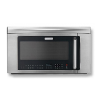
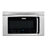
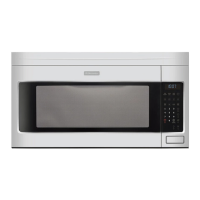
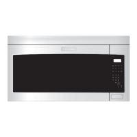
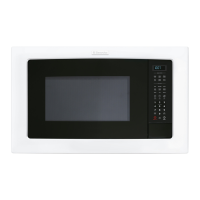
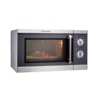
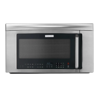
Detailed technical specifications of the microwave oven, including dimensions and features.
Instructions for proper grounding and electrical connection requirements for safe operation.
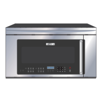
Diagrams illustrating the oven's external components and the control panel layout.
Explanation of component functions and sequence during oven's off and cooking modes.
Details on variable cooking, power reduction, sensor cooking, and their operational sequences.
Description of different methods for venting hot air from the microwave oven.
Detailed explanations of various internal components and their functions within the oven.
Explanation of touch control panel units, keyboard operation, and control unit functions.
Description of power, relay, buzzer, synchronizing, door sensing, and humidity sensor circuits.
Detailed explanation of the humidity sensor's detection circuit and its role in automatic cooking.
General troubleshooting guidance, important notes on fuses, and power disconnection procedures.
Step-by-step procedures for testing the magnetron and measuring microwave output power.
Procedures for testing the power transformer and high voltage rectifier for proper function.
Testing procedures for high voltage capacitors and thermal cut-outs/fuses.
Procedures to test secondary interlock switches, door sensing switches, and primary interlock relays.
Testing procedures for the monitor switch and troubleshooting steps for a blown monitor fuse.
Procedures for testing hood thermostats and the hood fan motor's operation and resistance.
Testing procedures for the touch control panel assembly, including keyboard and control unit diagnostics.
Identifying control unit issues and performing a keyboard glass unit test for defects.
Procedures for testing various relays and their operational voltage and connected components.
Procedures for checking blown fuses on the PWB and troubleshooting indicator light issues.
Testing the humidity sensor and performing water load cooking tests for proper operation.
Methods to test humidity sensor and control unit, including dummy resistor circuit usage.
Procedure to test the noise filter for proper resistance and continuity.
Precautions for handling electronic components and servicing the touch control panel.
Tools required for service and guidelines for using lead-free solder and soldering techniques.
Critical warnings regarding high voltage hazards and potential microwave energy exposure.
Precautions to prevent electric shock and guidelines for accessing components without removing the oven.
Procedures for removing the oven from the wall and accessing the hood louver and outer case.
Steps for removing the magnetron, high voltage rectifier, and high voltage capacitor.
Procedures for replacing the hood fan motor, duct, oven lamp socket, and humidity sensor.
Steps for removing the power transformer, hood fan thermostats, and turntable motor.
Procedure for removing and installing the cooling fan motor, including fan blade handling cautions.
Procedures for removing positive lock connectors, oven lamps, cook top lamp sockets, and stirrer antenna motors.
Steps for installing stirrer covers and removing panel assemblies, door switches, and related components.
Adjusting door sensing, interlock, and monitor switches and checking door play for proper alignment.
Procedure for replacing the oven door, including re-installation and post-service checks.
Detailed steps for disassembling the oven door, including choke cover and latch components.
Pictorial diagram of components and detailed circuit diagram for the power unit.
Circuit diagram for the glass touch key unit and the display unit, showing their interconnections.
Diagram illustrating the layout of components and connections on the printed wiring board.
| Brand | Electrolux |
|---|---|
| Model | EI30BM55HB |
| Category | Microwave Oven |
| Language | English |