This Manual has been prepared to provide Electrolux Service Personnel
with Operation and Service Information for ELECTROLUX MICROWAVE
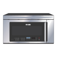
OVENS, EI30BM55HB, EI30BM55HS, EI30BM55HW and EI30BM55HZ.
Table of Contents
Basic Information
1-2
Section 1 Basic Information
.................................. 1-1
Table of Contents .................................................... 1-2
Safe Servicing Practices ........................................ 1-3
Warnings and Safety Information .......................... 1-4
Precautions To Be Observed Before And During
Servicing To Avoid Possible Exposure To Excessive
Microwave Energy .................................................. 1-5
Before Servicing ...................................................... 1-5
Danger Caution High Voltage ................................ 1-5
Before Servicing ...................................................... 1-6
Microwave Measurement Procedure .................... 1-7
Product Specification.............................................. 1-8
Grounding Instructions .......................................... 1-9
Oven Diagram .......................................................... 1-10
Section 2 Operation
................................................ 2-1
Operating Sequence Description .......................... 2-2
Hot Air Exhaust Ventilation Methods .................... 2-4
Oven Schematic-Off Condition .............................. 2-5
Oven Schematic-Cooking Condition .................... 2-5
Component Descriptions........................................ 2-6
Touch Control Panel Operation.............................. 2-7
Humidity Sensor Circuit.......................................... 2-8
Section 3
Troubleshooting and Testing ................ 3-1
Troubleshooting Guide .......................................... 3-2
Troubleshooting Guide Chart ................................ 3-3
Test Procedures ...................................................... 3-4
Section 4 Component Teardown .......................... 4-1
Servicing .................................................................. 4-2
Precautions for Using Lead-Free Solder .............. 4-3
Warnings .................................................................. 4-4
Removal of Oven From Wall .................................. 4-6
Hood Louver Removal ............................................ 4-6
Outer Case Removal .............................................. 4-6
Hood Fan Motor Removal ...................................... 4-6
Magnetron Removal ................................................ 4-7
High Voltage Rectifier & High Voltage Capacitor.. 4-7
Hood Fan Motor, Hood Duct, Oven
Lamp Socket and Humidity Sensor
Replacement ............................................................ 4-8
Power Transformer Removal .................................. 4-9
Hood Fan Thermostat (60ºC ON and
70ºC Off) Removal .................................................. 4-9
Turntable Motor Removal........................................ 4-9
Cooling Fan Motor Removal .................................. 4-10
Positive Lock ® Connector (No-Case Type).......... 4-11
Oven Lamp Removal .............................................. 4-11
Cook Top Lamp Socket .......................................... 4-11
Stirrer Antenna Motor Removal ............................ 4-11
Stirrer Cover and Stirrer Antenna
Installation................................................................ 4-12
Right Panel Assembly and Power Unit
Removal.................................................................... 4-12
Door Sensing Switch, Secondary Interlock Switch
and Monitor Switch Removal ................................ 4-12
Door Sensing Switch, Secondary Interlock Switch
and Monitor Switch Adjustment ............................ 4-13
Door Replacement .................................................. 4-14
Door Disassembly .................................................. 4-15
Section 5
Wire Diagrams ........................................ 5-1
Pictorial Diagram .................................................... 5-2
Power Unit Circuit.................................................... 5-3
Glass Touch Key Unit and Display Unit Circuit .... 5-4
Printed Wiring Board .............................................. 5-5