EasyManua.ls Logo

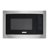
Electrolux EI30MO45GSA User Manual

Electrolux EI30MO45GSA
52 pages
To Next Page IconTo Next Page
Page #1 background imageLoading...
Page #1 background image
Publication #5995534665 P/N 316439275 April 2009
GRAIN DIRECTION
(ALL PARTS)
Technical Service Manual
Microwave Oven
Models
EI27MO45GSA
EI30MO45GSA

Other manuals for Electrolux EI30MO45GSA

Questions and Answers:

Electrolux EI30MO45GSA Specifications

General IconGeneral
BrandElectrolux
ModelEI30MO45GSA
CategoryMicrowave Oven
LanguageEnglish

Summary

Safe Servicing Practices

Microwave Safety Precautions

Microwave Exposure Avoidance

Steps to take before and during servicing to prevent exposure to microwave energy.

High Voltage Dangers

Warning about high voltage present in the microwave oven circuit.

Microwave Measurement Procedure (USA)

Requirements

Defines leakage limits and interlock switch requirements for USA.

Preparation for Testing

Steps to prepare instruments and load for microwave leakage testing.

Leakage Test Procedure

Procedure for performing a closed-door microwave leakage test.

Microwave Measurement Procedure (Canada)

Requirements

Defines leakage limits for microwave ovens in Canada.

Preparation for Testing

Steps to prepare instruments and load for microwave leakage testing.

Leakage Test with Enclosure Installed

Procedure for closed-door leakage testing with the oven enclosure.

Leakage Test Without Enclosure

Procedure for performing a leakage test with the oven enclosure removed.

No Load Test

Procedure for testing microwave leakage without a load.

Product Specification

Grounding Instructions

Oven Diagram

Operating Sequence Description

Variable Cooking

Sensor Cooking Condition

Cooking Sequence

Touch Control Panel Assembly

Door Open Mechanism

Explains how the door is opened via button and latch.

Door Interlock Switches

Describes the function and placement of door interlock switches.

Component Descriptions

Monitor Switch Operation

Details the monitor switch's function and failure modes.

Cooling Fan Motor

Description of the cooling fan's role in heat removal.

Turntable Motor Function

Description of the turntable motor's function for even cooking.

Safety Fuses

Explains the purpose of monitor, cavity temperature, and C/T fuses.

Humidity Sensor Circuit

Sensor Structure

Details the physical structure of the absolute humidity sensor.

Sensor Operational Principle

Explains how the humidity sensor circuit works based on moisture.

Sensor Detector Circuit

Describes the circuit that detects humidity sensor output for LSI control.

Troubleshooting Guide

Test Procedures

Magnetron Assembly Test

Details testing the magnetron assembly, including filament and short checks.

Power Transformer Test

Procedure for testing the power transformer's primary and secondary coils.

High Voltage Rectifier Test

Procedure for testing the high voltage rectifier diode.

High Voltage Capacitor Test

Procedure for testing the high voltage capacitor for shorts or opens.

Cavity Temperature Fuse Test

Procedure for testing the cavity temperature fuse.

C/T Fuse Test

Procedure for testing the C/T fuse.

Primary and Third Door Switch Test

Tests primary and third door switches for proper operation.

Door Sensing Switch Test

Tests the door sensing switch for correct operation when the door is open/closed.

Secondary Interlock Relay Test

Tests the secondary interlock relay for proper contact state.

Monitor Switch Test

Tests the monitor switch for correct operation based on door status.

Touch Control Panel Assembly Test

Outlines testing procedures for the touch control panel assembly.

Control Unit Test

Describes symptoms indicating a defective control unit.

Key Unit Test

Details testing the key unit for defects.

Relay Test

Tests the relays (RY1, RY2) for proper operation and voltage.

Defrost Test

Procedure for testing the defrost function.

Noise Filter Test

Procedure for testing the noise filter using an ohmmeter.

Outer Case Removal

Power Transformer Removal

High Voltage Rectifier and Capacitor Removal

Magnetron Removal

Oven Lamp and Socket Removal

Positive Lock Connector Removal

Fan Motor Removal

Servicing the Touch Control Panel

Servicing with Oven Power Supply

Procedure for servicing the touch control panel using the oven's power supply.

Servicing with External Power Supply

Procedure for servicing the touch control panel using an external power source.

Control Panel Assembly Removal

Key Sheet Replacement

Door Switch Removal

Door Switch Adjustment

Door Replacement

Sealer Film Handling

Turntable Motor Removal

Wiring Schematic Oven Off Condition

Pictorial Diagram

Wiring Diagram

Electrical Parts

Cabinet Parts

Control Panel Parts

Oven Parts

Door Parts

Screws, Nuts and Washers

Related product manuals