8
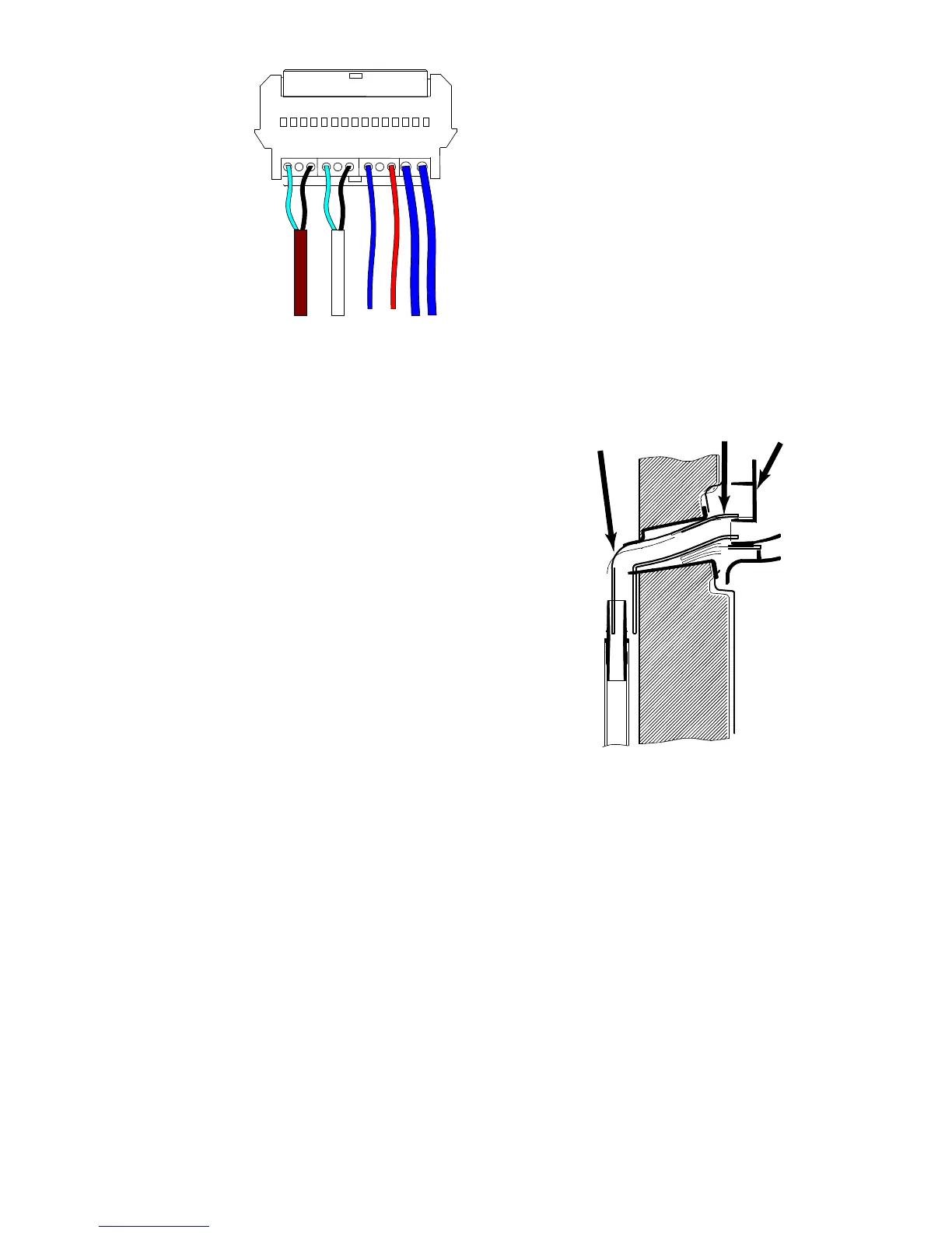
Connection of components (picture 5):
E. Evaporator sensor (brown)
C. Air sensor (white)
F. Fan
B. Defrost heater
The reassemble is done in the opposite order.
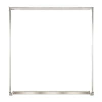
NOTE! Before the cover, the insulation and the
upper air channel is reassembled, check that the
cage (G) for the drainage hose is not loose from
from the module (H). Check also that the corrugated
drainage hose (J) is pressed against the
module (picture 6).
E C F B