Technical Support - A.D.L. 48/70 599 74 23-12 Rev.00
How to check collector motors
1) Check the connection blocks (wiring) and for the
presence of any protruding/kinked terminals.
2) Check for the presence of any marks / residue /
water or detergent deposits on the motor and where
these come from.
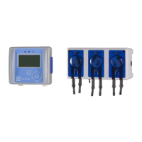
3) Proceed by checking for any windings / earthed
parts or parts with poor earthing insulation. Use a
tester with a minimum capacity of 40 MΩ: between
each individual terminal and the motor casing, read
∞ (Fig. 10)
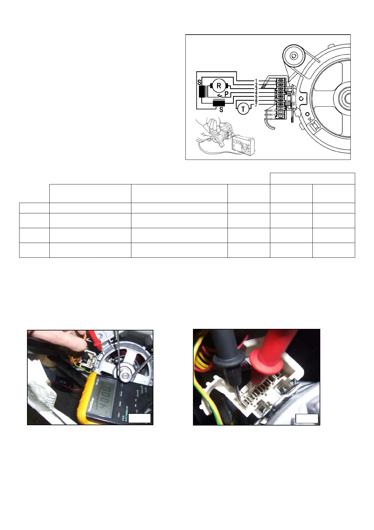
4) Proceed by checking each individual winding
according to the following table (Fig. 11).
MOTORS
MOTOR TERMINAL
BOARD TERMINALS
CHECK:
NMSC AP&C ECM
A
6 - 7 Tachometric generator winding 184 68.7 91
B
2 – 5
Stator winding
(Full field)
1.1÷2.2 1.62÷2.12 1.46÷1.95
C
3 – 4
Rotor winding
(plus thermal cutout)
1.6÷1.8 1.9÷2.42 2÷2.3
D
1 – 5
Stator winding
(half field)
0.55÷0.56 0.67 0.68
The tolerance of the resistance of windings is ± 7%
Note: when checking the rotor winding, the measurement must be made along the entire profile, turning the shaft very
slowly and checking for the presence of any short circuits between visible blades. Also check the condition of the
brushes.
P = motor protector
R = rotor S = stator
T = tachometric generator
Fig. 10
Fig. 11