Service
Manual
23
23. Programme unit
6
438 9145-41/03
03.11
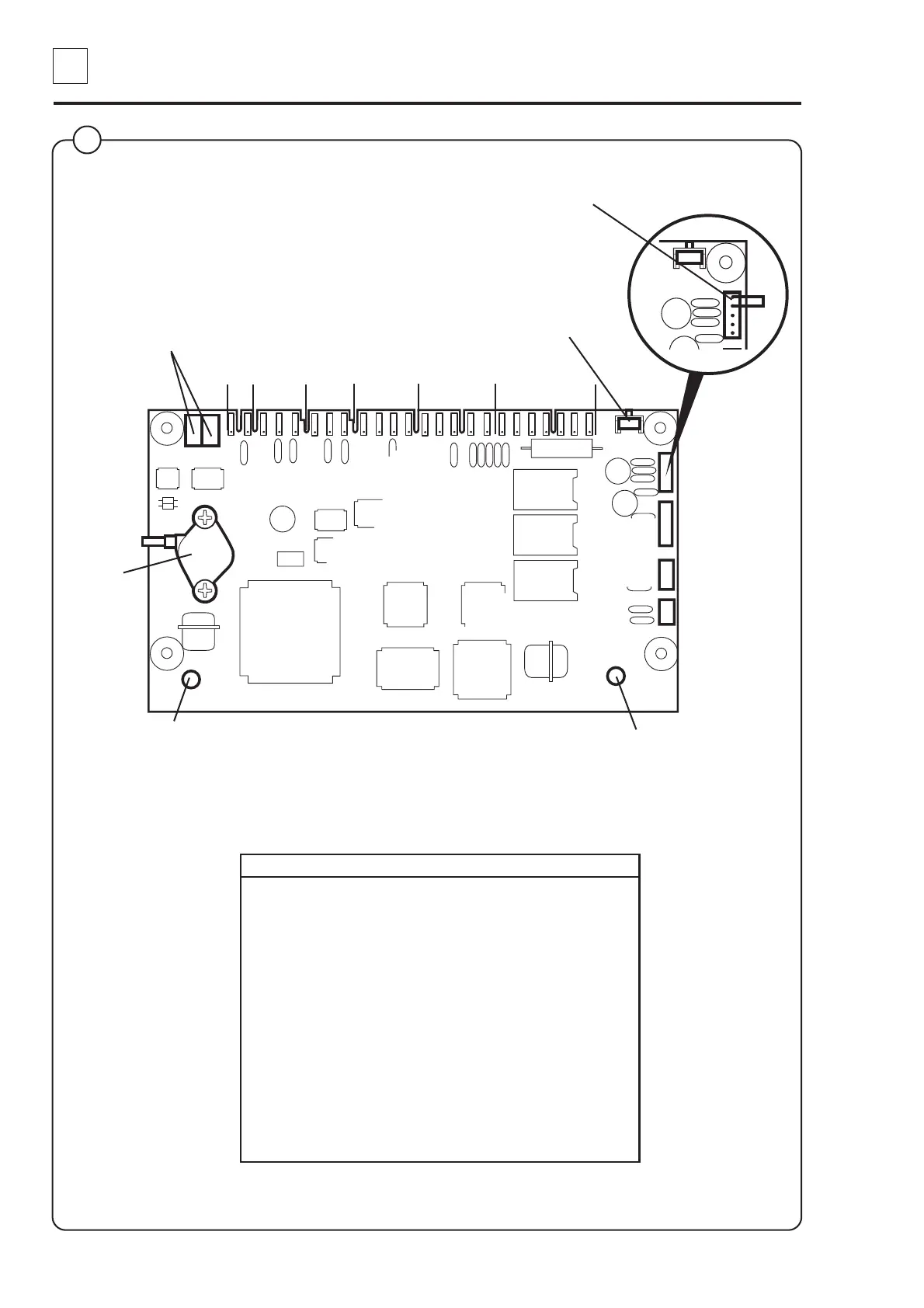
X7
X1 X2 X3 X4 X5 X6
X7
X8
X9
X10
Red LED:
Continuous red light = voltage
supply OK
Green LED:
Quick blinks = communication
between CPU card and I/O card.
(Not for FOM71 CLS).
Pushbutton SW1: used as an
acknowledgement button when in the
Service programme mode (the same
function is also available on the
communication card).
The two pins in switch X7 are shorted to confirm
changes made in Configuration 1 and 2.
Card Switch Function
X1 Input from water temperature sensor
X2 not used
X3 not used
X4 Output to motor controller
X5: 1-3 Serial communication with I/O card 1
X5: 4-5 Voltage supply from I/O card 1
X6: 1-5 Serial communication with display card
X6: 6-7 Voltage supply to display card
X7 PC communication
X8 Motor communication (reserved)
X9 Scale communication
X10 Internal communication (not used)
Pressure
sensor
3972
2 1 3 2 1 3 2 1 4 3 2 1 5 4 3 2 1 7 6 5 4 3 2 1
P1, P2Used for factory
calibration of the
pressure sensor.
3