Page 4
INDIVIDUAL COMPONENTS AND THEIR RESISTANCE VALUES
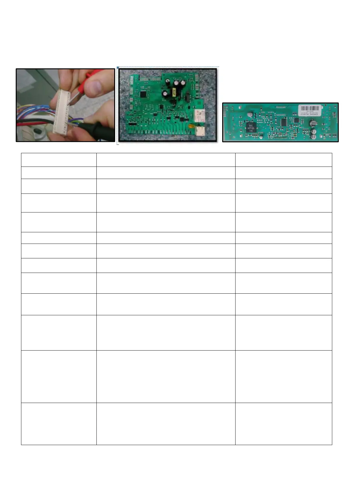
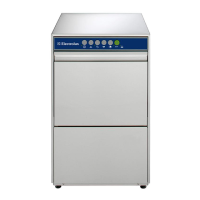
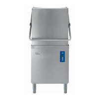
You can measure the components either on the PCB connectors or directly from the
component. Measuring from the connectors of the PCB gives definitive results to define the
repair suited. Using the Component Resistance Values from the table below, you can
determine the failed component.
LEGEND: KN = Connector, (e.g. KN2.1 = Connector 2, Position 1)
COMPONENTS REAL VALUES NOTES
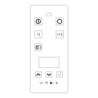
ON/OFF Button 0 on component - On/Off Button Is Pressed
Door Switch KN2.9 – KN2.2 0 - Door Is Closed
Pressure Switch
KN2.10 – KN2.2 0
- There is Water in Sump
- There is no Water in Sump
Drain Pump
KN2.2 – KN2.4 143 ± 10 (Hanyu)
210 ± 12.6 (Hanning)
Water Inlet Valve KN2.6 – KN 2.9 3750 ± 375 (20ºC )
Diverter KN6.1– KN 2.9 6840 ± 342
Turbo Fan Motor KN6.2– KN 2.9 238.6 ± 11.9
Heater
23.95 ± 15
- Measured Just on the
Component
Detergent Dispenser 4450 ± 10 (25 ºC)
- Measured Just on the
Component
Recirculation Wash
Pump
KN2.3 – KN2.9 95 ± 6.65
126 ± 8.8
- Primary Winding
(on PCB Connector)
- Secondary Winding
(Just on the Component)
NTC Sensor
( Relative to water
temperature ºC )
KN 7.3-KN 7.4 25°C – 5000 ± 250
35°C – 3300 ± 181.5
55°C – 1520 ± 98.8
63°C – 1174 ± 88.0
80°C – 670 ± 53.5
90°C – 488 ± 41.5
Float Switch
KN2.1 – KN 2.5 0
KN2.1 – KN 2.4
- Micro Switch Is Inactive
(No Water Present)
- Micro Switch Is Active
(There is Water Present)