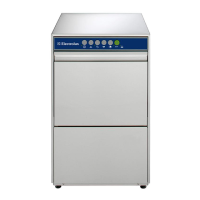
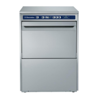
Do you have a question about the Electrolux WSF67251S and is the answer not in the manual?
Procedure to enter the service test mode.
Details of service test steps and their tested loads.
Specifications and resistance values for wash and drain pumps.
Specifications for heater casing and pump coil resistance values.
Specifications for detergent dispenser and pressure switch.
Resistance values of the NTC sensor at different temperatures.
Resistance value and description of the diverter component.
Operation description and continuity values for the float switch.
Continuity value for the door switch when closed.
Resistance value and specifications for the fan motor.
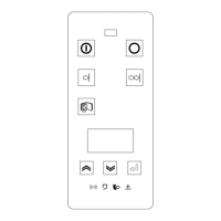
Specifications for rinse aid sensor and ON/OFF button.
Specifications for the brushless DC circulation pump motor.
Voltage, frequency, power, flowrate, and resistance of the drain pump.
Specifications for the heater casing group, including heater and NTC.
Specifications for pressure switch and diverter.
Specifications for detergent dispenser and rinse aid components.
Specifications for the hose inlet valve safety assembly.
Specifications for door lock mechanism and ON/OFF button.
Specifications for fan motor and EMC filter.
Specifications for flowmeter and power cord.
Maximum height and length of the drain hose.
Description of the hose inlet valve safety fitting assembly.
Function of the air break in measuring water input.
Description of the sump as a water reservoir.
Function of the lower spray arm support.
Function of the upper spray arm feed tube.
Function of the upper spray arm channel feed.
Function of the upper basket spray arm.
Function of the lower spray arm.
Steps to remove the worktop and plastic kick plate.
Procedure for removing the side panels.
Steps to remove the front panel and metal kick plate.
Steps to remove control panel and electronic card.
Steps to remove PCB box cover and door lock group.
Steps to remove dispenser and door inner/hinge group.
Steps to remove the door inner and hinge cord group.
Steps to remove lower, upper, and cutlery baskets.
Procedures for removing micro and metal filters.
Steps to remove the basket rails.
Procedures for removing lower and upper spray arms.
Detailed steps for removing the sump assembly.
Steps to access and remove the motor fan.
Steps to access NTC and air break components.
Steps to access and remove the cover valve inlet.
Steps to access and disconnect the supply cable.
Steps to access and remove the drain pump from the front.
Steps to remove the tray spillage.
Steps to remove the circulation pump through the base.
Steps to remove the heater group.
Steps to access water softener and EMC filter.
Steps to access and remove the float switch.
Steps to remove the drain hose.
| Brand | Electrolux |
|---|---|
| Model | WSF67251S |
| Category | Dishwasher |
| Language | English |