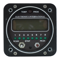
a) Swt. #1: Set this switch DOWN if you wish to scan 8 channels. Set this switch UP if you wish to
scan only 6 cylinders.
b) Swt. #2: If you have a 6-cylinder engine, the first 6 channels should be used for EGT or CHT
analysis. Therefore, set this switch DOWN. If you have a 4-cylinder engine, set this switch UP.
c) Swt. #3: Set this switch DOWN to enable the Differential Warning feature. If you plan on using
the first 4 or 6 analyzer channels of the Smart Analyzer for measuring many different kinds of tem-
peratures, you will want to disable this feature (set this switch UP).
d) Swt. #4,
EGT Analysis: If the first 4 or 6 channels are to be used for EGT analysis and you have a
fuel-injected engine, set this switch DOWN. This will set the Differential Warning limit to 95F (i.e.,
if the EGT difference between the hottest and coldest cylinder exceeds 95F, the warning light will
come on). Some fuel-injected engines have normal EGT differences as high as 150'F (some IO-520's,
IO-540's and IO-470's). Each engine has its own unique operating characteristics.
If you have a carbureted engine or a fuel-injected engine with a normal EGT difference greater than
95'F, set this switch UP. This will set the Differential Warning limit to 195F. Carbureted engines do
not distribute the fuel to the cylinders as well as most fuel-injected engines and generally have a wider
EGT spread. If you find your EGTs are always within 95F (hottest to coldest cylinder), you may
want to set this switch DOWN for better sensitivity.
e) Swt. #4,
CHT Analysis: If the first 4 or 6 channels are to be used for CHT analysis, set this switch
DOWN. This will set the Differential Warning limit to 95F. The temperature of a particular cylinder
is a function of the air flowing over that cylinder, the temperature of the adjacent cylinders and the fuel
distribution to that cylinder. Note: The automatic leaning feature only works when the first 4-6
channels are used to monitor EGT's.
3. CHT Probe Installation:
A single CHT probe should be placed on the hottest cylinder. In a 6-cylinder engine this would be one of the
center cylinders. On a 4-cylinder engine this would be one of the back cylinders.
If a second CHT probe is to be installed it should be placed on one of the front unobstructed cylinders. This
will allow you to detect shock-cooling during descents.
Most engines have a port just below the lower spark plug for the CHT probe.
If your engine has a primary
CHT probe in one of the cylinders, do not remove it. The SR-8A is not STC'd as a primary replacement
instrument. Select another cylinder for your probe. If youre putting a CHT probe on every cylinder use our
P-102 Gasket CHT Probe for your primary cylinder.
10
Installation Instructions 2. Instrument Setup: