Do you have a question about the Electronics International SR-8A and is the answer not in the manual?
Lists conditions under which the warranty does not apply, such as misuse or improper installation.
States the warranty does not extend to connected devices or systems.
Defines the manufacturer's obligation as repair, replacement, or refund at their discretion.
Manufacturer is not responsible for shipping charges or damages incurred.
No representative can assume liability beyond the stated warranty terms.
Allows product return within thirty days for a refund if warranty terms are not accepted.
Disclaims implied warranties and liability for consequential damages.
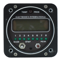
Introduces the Smart Analyzer's capabilities and features.
Explains the 8 channels, analyzer channels, and temperature measurement options.
Details the Manual, Step, and Scan modes of the mode select switch.
Describes how the indicator shows the hottest cylinder during scan mode.
Explains the 'Temp Prob' warning light in Manual and Scan modes.
Explains the 'DC' indicator for temperature spread exceeding limits.
Details how to adjust the scan rate using a screwdriver.
Explains the purpose and use of the Peak Locate button.
Describes controlling display backlight and channel indicator intensity.
Provides guidance on operating the analyzer during different flight phases.
Recommends Manual Mode during taxi to avoid false warnings.
Suggests manual or scan mode for checking temperatures during run up.
Recommends Scan Mode during takeoff and notes potential 'Temp Prob' light.
Recommends Scan Mode for automatic diagnosis during climb.
Discusses engine leaning during cruise for efficiency and health.
Details the steps for rough leaning using the analyzer.
Explains how to perform precision leaning for optimal EGT.
Describes how to find the cylinder that peaks first for verification.
Recommends Manual Mode during descent to check for shock-cooling.
Crucial pre-installation steps, including warranty, mechanic familiarity, and approvals.
Explains setting the four switches on the back panel for aircraft configuration.
Details the settings for switches 1, 2, 3, and 4 for different engine types and features.
Instructions for installing CHT probes on the hottest and other cylinders.
Guidance on installing EGT probes in exhaust stacks, including location and hose clamp retightening.
Instructions for installing TIT probes on the turbo-charger inlet.
Details for installing oil temperature probes on Lycoming engines.
Instructions for installing oil temperature probes on engines with a 5/8"-18 oil drain plug.
Guidance for installing a carburetor temperature probe in the carburetor housing.
Instructions for mounting the Outside Air Temperature probe in an appropriate location.
Explains how to mark extension cables with their function using heat shrink.
Instructions for routing the Circular Connector from the instrument panel.
Guidance on routing extension cables to probes and handling excess length.
Details on attaching Red Slip-on and Yellow Precision connectors to extension cables.
Instructions for connecting power, ground, and dimming wires.
Steps for physically mounting the instrument panel using screws.
Procedure to test the instrument and connections after installation.
Steps to diagnose potential instrument problems by checking inputs and power.
Methods for testing the probes using an ohmmeter or swapping channels.
Steps to diagnose issues with extension cables, including poor connections and crimps.
Lists key specifications like model, weight, power, display, accuracy, and probe types.
Summarizes features like scan rate, peak locate, hottest cylinder indicator, and warning lights.
Outlines the steps to add an extension cable to an unused channel.
Provides diagrams of the Extension Cable and Connecting Cable harnesses' circular connectors.
| Brand | Electronics International |
|---|---|
| Model | SR-8A |
| Category | Measuring Instruments |
| Language | English |