Do you have a question about the Electronics International FP-5 and is the answer not in the manual?
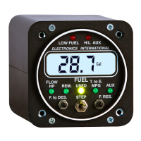
Describes the digital LCD display and LED indicators for mode indication and warnings.
Details Low Fuel and High/Low Fuel Pressure warning LED functions and indications.
Describes the self-diagnostics test and initial LED flashing upon aircraft master switch activation.
Covers FLOW, REM, USED, T. to E., PRESS, F. to D. (FP-5L only), and F. Reserve (FP-5L only) modes.
Configuration of Full Fuel Level, K Factor, Filter, Display Update Time, and Loran/GPS Interface.
Programming for FLOW, REM, USED, T. to E., and PRESS modes, including alarms.
Provides the physical case dimensions of the FP-5 and FP-5L instruments.
Lists the weight of the unit, pressure transducer, and flow transducer.
States compliance with TSO C44a/C47 environmental standards.
Specifies the voltage and current requirements for operating the FP-5/FP-5L.
Explains how the intensity of green display mode LEDs is controlled via dimming wire.
Describes when the red Low Fuel Warning LED blinks or stays on for reminders and warnings.
Details when the H/L Fuel Pressure Warning LED blinks for high or low pressure limits.
Notes LCD visibility in sunlight and backlight control for night operation, showing '8888' on power up.
Specifies grounding behavior when warning LEDs are active and current limitations.
Provides accuracy figures for Fuel Flow (2% or better) and Pressure (2%) per TSO standards.
Details the display resolution for Fuel Flow, Remaining, Used, Time to Empty, and Pressure.
Lists the maximum displayable ranges for Fuel Flow, Remaining, Used, Time to Empty, and Pressure.
Summarizes the programmable modes available for Power-up, FLOW, REM, USED, T. to E., and PRESS.
Details the serial input port configurations and protocols for the FP-5L model.
Details the serial output port configurations and protocols for the FP-5L model.
Provides specifications for the FT-60 fuel flow transducer, including range, K Factor, and pressure drop.
Provides specifications for the FT-90 fuel flow transducer, including range, K Factor, and pressure drop.
Details specifications for the PT-100GA fuel pressure transducer, including range and pressure limits.
| Brand | Electronics International |
|---|---|
| Model | FP-5 |
| Category | Measuring Instruments |
| Language | English |