4
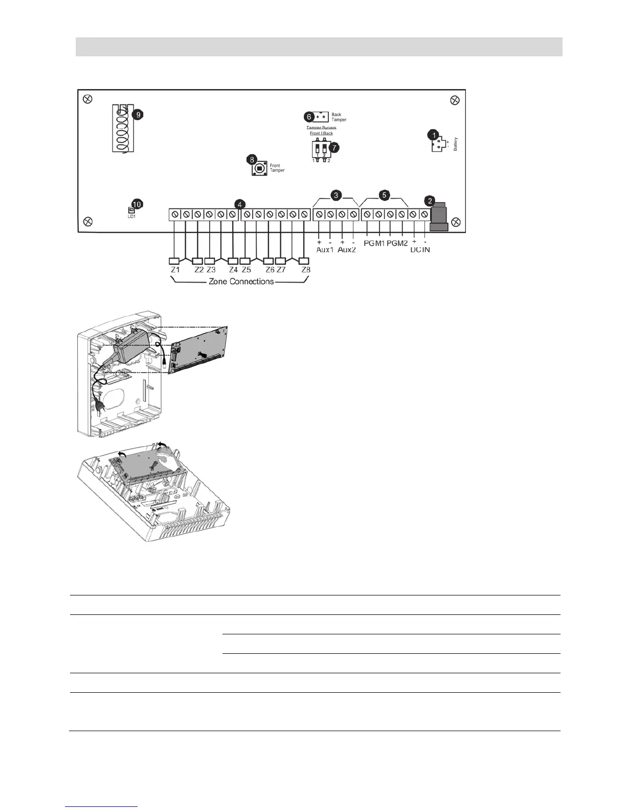
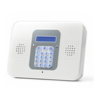
3. 2-Way Wireless I/O Expander Module Main Components
Backup battery connector
Power input jack (by external AC/DC adaptor)
Auxiliary parallel outputs (Aux1-2) for powering
detection devices
Zone inputs (loop type configurable in programming)
Programmable outputs (PGM): dry contact
Back tamper switch connector
Tamper bypass dip switch
Front case tamper switch
Antenna (868 or 433)
LED indicator
Figure 3-1: 2-Way Wireless I/O Expander Module circuit board and plastic unit
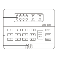
3.1. LED Indication
LED State Description
Red On AC and batteries OK
Flashing AC trouble
Off Power not present
Orange Flashing Low battery
Green/Red (tamper open) Flashing Green – Signal reception
Red – Signal transmission