7
GB
IRL
5 10152025303540 m
3
/min
300 600 900 1200 1500 1800 2100 2400 m
3
/h
Volumetric flow rate V
.
dB(A)
Sound pressure
level L
A
85
80
75
RD 62 50 Hz
5 10152025303540 m
3
/min
300 600 900 1200 1500 1800 2100 2400 m
3
/h
Volumetric flow rate V
.
dB(A)
Sound pressure
level L
A
85
80
75
RD 62 60 Hz
5 10152025303540 m
3
/min
300 600 900 1200 1500 1800 2100 2400 m
3
/h
Volumetric flow rate V
.
dB(A)
Sound pressure
level
L
A
90
85
80
75
RD 64 50 Hz
5 10152025303540 m
3
/min
300 600 900 1200 1500 1800 2100 2400 m
3
/h
Volumetric flow rate V
.
dB(A)
Sound pressure
level L
A
90
85
80
75
RD 64 60 Hz
5 10152025303540455055
300 600 900 1200 1500 1800 2100 2400 2700 3000 3300
Volumetric flow rate V
.
dB(A)
Sound pressure
level L
A
95
90
85
80
RD 65 50 Hz
m
3
/min
m
3
/h
5 10152025303540455055
300 600 900 1200 1500 1800 2100 2400 2700 3000 3300
Volumetric flow rate V
.
dB(A)
Sound pressure
level L
A
95
90
85
80
RD 65 60 Hz
m
3
/min
m
3
/h
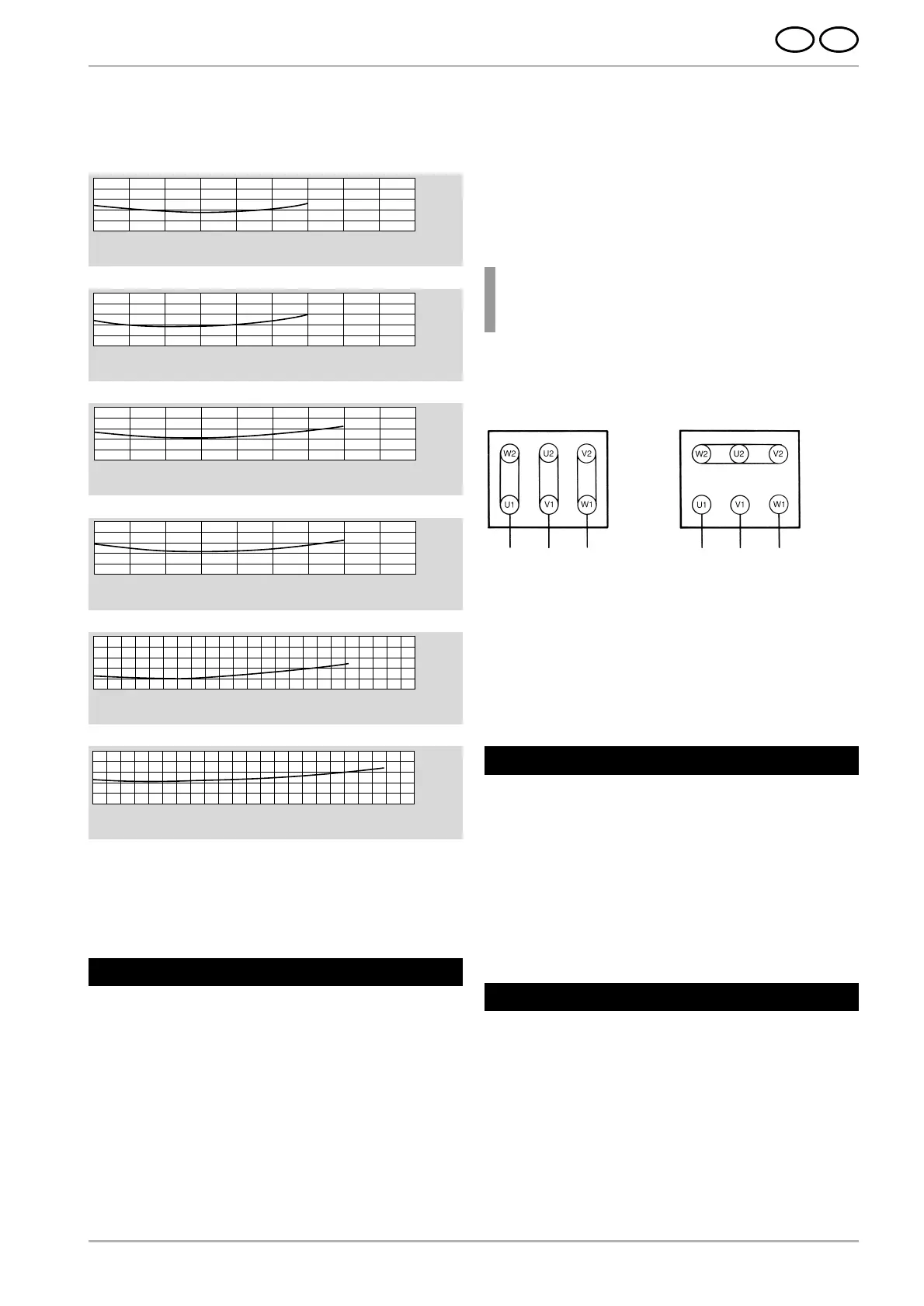
2.6 Generation of noise
The noise generated by a blower is not constant over the whole
performance curve (see diagrams below).
In certain unfavourable cases a sound-absorbing device may
be required (measurements by the operator are recommended).
Sound-absorbing measures are to be carried out by the opera-
tor so as not to exceed the legally permitted peak values at the
work places near the blower.
3.1 Transport
● Check all parts for damage during transport before installati-
on and starting of operation.
● Do not store the blower unprotected in the open (protect
against moisture).
● Attach hoist securely. Only use hoists and load suspension
devices with sufficient load-carrying capacity.
3.2 Installation, assembly
● Install the blower horizontally and weather-protected.
● Do not subject the blower to any vibrations or shocks.
● Blower with foot base; to be secured tightly at site of
operation on solid, even ground.
● Open intake and discharge ports are to be protected by wire
guards in accordance with DIN EN ISO 13857.
3 Installation
3.3 Electrical connection
Note!
The work described under this section may be
executed by a qualified electrician only. Connections
to be carried out in accordance with wiring diagram
in terminal box and relevant local regulations.
Checking direction of rotation
Start operation of blower.
The direction of rotation of the impeller must correspond to
the directional arrow on the housing. If the direction of rotation
is incorrect, the two connecting wires L1 and L3 have to be
interchanged.
If the rated current of the drive motor is exceeded during opera-
tion, voltage and frequency of the power supply should be
checked and compared with the data on the blower rating plate.
If the blower cannot be operated over the whole range of the
characteristic curve, an overload of the motor may occur in
case of insufficient system resistance (excessive current con-
sumption). The volumetric air flow should be reduced in this
case by means of a throttle valve fitted on the intake or dischar-
ge side.
The blower must not be subjected to vibration or shock loads.
4 Operation
Wearing parts are subject to the recommended maintenance
intervals and are a constituent part of the applicable warranty
claims. The service life of wearing parts (ball bearings and filters)
depends on the operating hours, the load and other influences,
such as temperature, etc.
5.1 Ball Bearings
The fan is equipped with enclosed deep groove ball bearings,
which do not have be to re-greased and have a minimum service
life of approx. 22,000 hours. We recommend exchanging the
ball bearings before the end of service life (at least 22,000 hours).
The 30-month operating time is not to be exceeded given con-
tinuous operations of 24 hours a day.
5 Maintenance
L1 L2 L3
(L3) (L1)
-configuration
(lower voltage)
L1 L2 L3
(L3) (L1)
-configuration
(higher voltge)
☛
● Ensure adequate motor ventilation. Permissible ambient
temperatures for:
Standard motors –20° C to +60° C
with a rated voltage (max. ±10 % voltage tolerance) and a
rated frequency of 50 Hz or 60 Hz
Special-purpose motors –20° C to +40° C
multi-voltage range (50 Hz and/or 60 Hz)
FU/FUK series
UL approval
As drive motor a three phase a.c. motor has been attached.
● The drive motor has to be safeguarded by a motor circuit-
breaker.
● The safety earth terminal can be found in the terminal box.
 Loading...