9
the given relay is established in the condition determined in parameters rL1, rL2, rL3, rL4
individually for each setting of each channel.
rL1 = 0, rL2 = 0, rL3 = 0 or rL4 =0 - the appropriate relay is switched off;
rL1 = 1, rL2 = 1, rL3 = 1 or rL4 =1 - the appropriate relay is switched on.
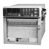
5.1.8. The keyboard and indication module structure includes:
1) Six green round LEDs (Lighted Electric Diode) displaying the indication mode of the basic
four-digit indicator; the button MODE allowing to choose one of six modes of operation:
• cyclic interrogation of channels on the measured quantity (indication time of one
channel is set from 2 up to 100 seconds);
• Manual interrogation of channels on the measured quantity;
I setting indication I;
II setting indication II;
III setting indication III;
IV setting indication IV.
2) Six round green LEDs displaying the channel number; the choice of the channel is made
with the button CHANNEL.
3) Six triangular LEDs displaying the relay RMT condition.
LEDs display the relay setting
condition III, IV, and LEDs ▼ display the relay setting condition I, II:
• The red color displays the operation of the emergency setting relay IV, I
independently from the condition of the relay III, II accordingly;
• The yellow color displays the condition of the precautionary setting relay III, II.
To provide a correct logic working of indication it is necessary to establish the setting
significance in the following order: UStI < UStII < UStIII < UstIV.
4) Buttons «PGM», ">", "▲", are used for the input of setting, configuration parameters and
realization of calibration of the line resistance at the two-wire diagram of circuit connection of
resistance thermal converters and R0 of the equalizer for thermoelectric converters. One pressing to
the button of a choice of the edited category ">" provides moving of the edited (blinking) category to
the right. One pressing to the button "▲" provides significance changing of the edited category per
unit or it chooses the following configuration parameter.
5.1.8.1. For programming of settings:
• display into indication the edited setting value with the help of buttons MODE and
CHANNEL;
• press the button "PGM" for beginning of setting value programming;
• edit the setting value with the help of buttons ">", "▲" according to article 5.1.8.4);
• finish the setting editing by pressing the button "PGM".
5.1.8.2. For configuration parameters programming:
• in the mode of cyclic or manual interrogation of channels, press the button "PGM",
then on the indicator the header "PScF" will be highlighted - the password inquiry;
• enter the password with the help of buttons ">", "▲" according to article 5.1.8.4); if
the entered password is correct, a mnemonic designation of the first configuration parameter will be
displayed; if the password is wrong, RMT will come back to the previous mode of operation. If the
password is equal to 0, the pressing of the button "PGM" will result at once in indication of the first
configuration parameter;
• choose the necessary parameter with the button "▲";
• choose the necessary channel with the button CHANNEL;
 Loading...