-30-
Connect the wires according to the Wiring Checklist and
press the switch while turning the variable resistor from
right to left (from 0W to 50KW). The 100KW and variable
50KW are a voltage divider that sets the voltage at the
transistor base. If this voltage is less than 0.7V then the
transistor will be off and no current will flow through the
LED. As the base voltage increases above 0.7V a small
base current starts to flow, which is amplified to produce
a larger collector current that lights the LED. As the base
voltage continues to increase the transistor becomes
saturated and the LED brightness will not increase
further.
This circuit will normally be used with the voltage divider
set so that the transistor is turned on but is not saturated.
Although this circuit does not have many applications by
itself, when a small alternating current (AC) signal is
applied to the base then a larger copy of the signal will
appear at the collector - a small-signal amplifier!
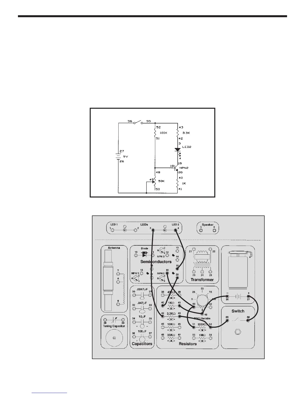
EXPERIMENT #16: Standard Transistor Biasing Circuit
Wiring Checklist:
o 27-to-56
o 55-to-52-to-43
o 42-to-3
o 4-to-19
o 18-to-48-to-51
o 20-to-40
o 41-to-49-to-26
Schematic