-60-
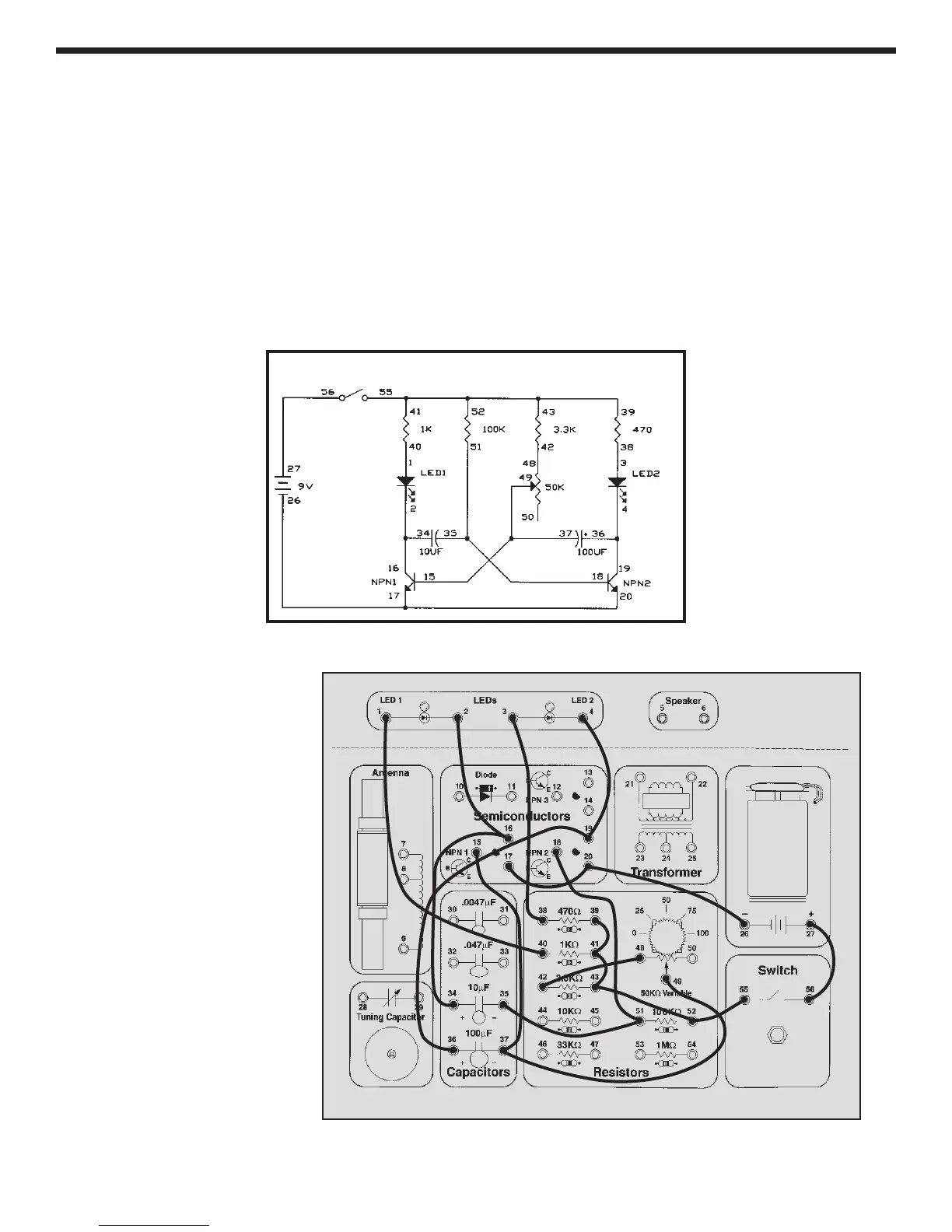
Take a look at the schematic. This circuit configuration is
a type of oscillator called an astable multivibrator. What
do you think it will do? Connect the wires according to
the Wiring Checklist, noting that the transistor bases are
not connected although their wires cross in the
schematic. Initially set the variable resistor (VR) to its
minimum value (turn it to the right). Press the switch and
hold it down. One LED is on while the other is off, and
they change about every second. What do you think will
happen as you turn the knob on the VR? The right LED
stays on longer than the left one.
In this circuit, one transistor is always on while the other
is off. In this type of oscillator there is no inductor, the
frequency is controlled only by the resistors and
capacitors. The 100KW and 10mF determine how long
NPN1 is on and the 3.3KW, VR, and 100mF determine
how long NPN2 is on. If you want to experiment with
changing part values, go ahead. But don’t replace the
capacitors with the smaller disc ones (you’ll see why in
the next experiment).
Blinking lights like this are often used to attract people’s
attention.
EXPERIMENT #41: Blinking Lights
Wiring Checklist:
o 27-to-56
o 55-to-52-to-43-to-41-to-39
o 40-to-1
o 2-to-16-to-34
o 35-to-51-to-18
o 38-to-3
o 4-to-19-to-36
o 15-to-37-to-49
o 48-to-42
o 17-to-20-to-26
Schematic