ASSEMBLY INSTRUCTIONS
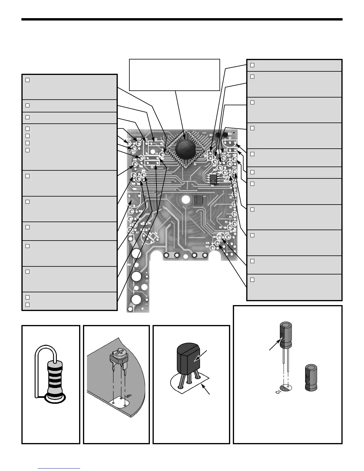
Identify and install the following parts as shown. After soldering each part, mark a check þ in the box provided.
Be sure that solder has not bridged to an adjacent pad.
Figure B
Figure A
Stand resistor on
end as shown.
Solder and cut off
the excess leads.
R14 - 100kΩ 1% 1/4W Resistor
(brown-black-black-orange-brown)
(see Figure A)
C2 - 0.22μF (224) Mylar cap.
C3 - 0.1μF (104) Mylar cap.
R32 - 1MΩ 1% 1/4W Resistor
R30 - 1MΩ 1% 1/4W Resistor
R31 - 1MΩ 1% 1/4W Resistor
R15 - 1MΩ 1% 1/4W Resistor
(brown-black-black-yellow-brown)
(see Figure A)
R16 - 220kΩ 1% 1/4W Resistor
(red-red-black-orange-brown)
(see Figure A)
R18 - 100Ω 1% 1/4W Resistor
(brown-black-black-black-brown)
(see Figure A)
VR1 - 200Ω (201) Potentiometer
(see Figure B)
R11 - 20.5kΩ 1% 1/4W Resistor
(red-black-green-red-brown)
(see Figure A)
R10 - 9kΩ 1% 1/4W Resistor
(white-black-black-brown-brown)
(see Figure A)
C4 - 0.1μF (104) Mylar cap.
C5 - 0.1μF (104) Mylar cap.
Mount the potentio-
meter to the PC board
as shown.
C6 - 100pF (101) Discap
R17 - 100kΩ 1% 1/4W Resistor
(brown-black-black-orange-brown)
(see Figure A)
R23 - 470Ω 1% 1/4W Resistor
(yellow-violet-black-black-brown)
(see Figure A)
R28 - 220kΩ 1% 1/4W Resistor
(red-red-black-orange-brown)
(see Figure A)
Q2 - 2SA9015 Transistor
(see Figure C)
C7 - 220pF (221) Discap
R29 - 220kΩ 1% 1/4W Resistor
(red-red-black-orange-brown)
(see Figure A)
R24 - 1MΩ 1% 1/4W Resistor
(brown-black-black-yellow-brown)
(see Figure A)
R22 - 47kΩ 1% 1/4W Resistor
(yellow-violet-black-red-brown)
(see Figure A)
C1 - 2.2
μF
50V Electrolytic cap.
(see Figure D)
R19 - 10Ω 1% 1/4W Resistor
(brown-black-black-gold-brown)
(see Figure A)
NOTE: The 7106 IC1 is already installed
on the PC board. This type of installation
is called C.O.B. (chip on board). The
LM358 U2 IC is also mounted and uses
a surface mount package.
Figure D
Be sure that the negative (short) lead is
in the correct hole on the PC board.
Warning:
If the capacitor is connected with incorrect
polarity, it may heat up and either leak, or
cause the capacitor to explode.
Polarity
mark
(–)
(+)
Figure C
Flat
Top legend marking
on PC board
Mount the transistor with
the flat side in the same
direction as the marking on
the PC board as shown.
-4-