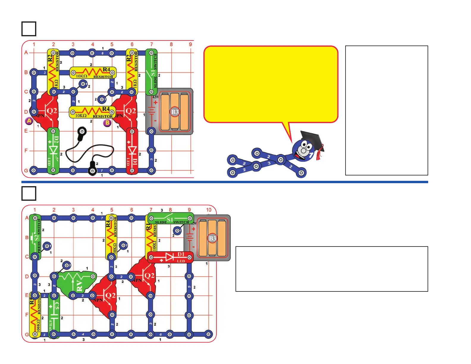
Project A11
Build the circuit, leaving
one end of the black
jumper wire unconnected.
Turn on the switch (S1).
One LED (D1 or D2) will
be on, the other off.
Alternately touch the
loose end of the black
jumper wire to the snaps
marked “A” and “B” in the
drawing. When you do,
both LEDs change
between on and off. One
LED “flips” on and the
other “flops” off.
Flip-Flop
Project A12
Build the circuit, turn on the slide switch (S1), and push the press
switch (S2). The red LED (D1) will be on for a little while. Push
the press switch again to turn the LED back on. Move the lever
on the adjustable resistor (RV) to adjust how long the LED stays
on for.
Adjustable Light Timer
-19-
This circuit is known as a “flip-flop” due to the way
it operates. Variations of this circuit form one of
the basic building blocks for computers. This
circuit can be thought of as a memory because it
only changes states when you tell it to, it
“remembers” what you told it to do, even though
you removed the loose wire. By combining
several of these circuits, you can remember a
letter or number. A typical computer has
thousands of flip-flops, in miniaturized form.
 Loading...