-45-
Project B12 Basic Light Meter
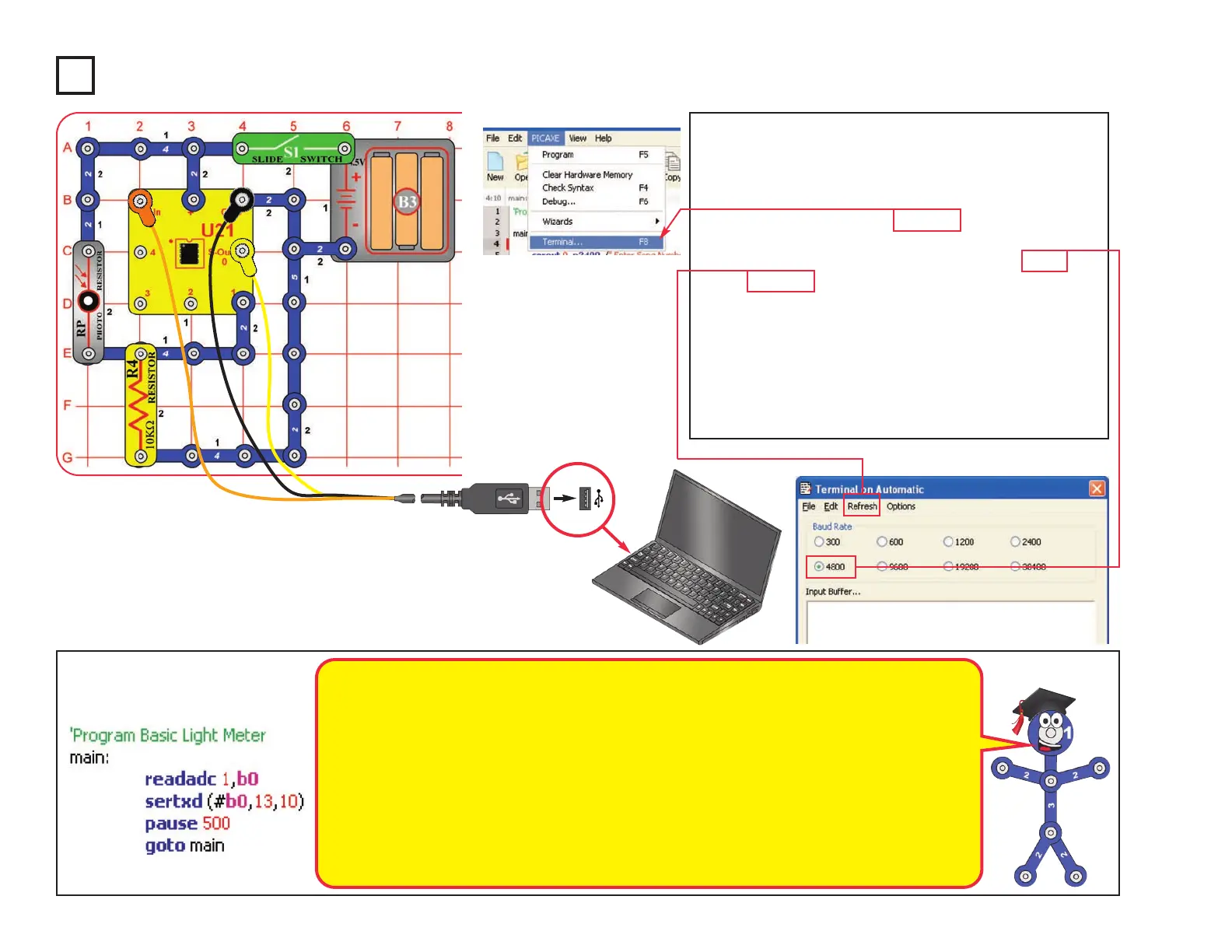
Build the circuit as shown. Turn on the slide switch
(S1). Load program Basic Light Meter into the
microcontroller (U21) using the programming
instructions in project B1.
Press the F8 key or select Terminal under the PICAXE
menu to open a terminal window for communication
with the microcontroller, set the baud rate to 4800, and
select Refresh. Turn the slide switch (S1) off and on to
reset the microcontroller.
The microcontroller measures the amount of light on
the photoresistor (RP), then displays it as a number in
the Terminal (0 is total darkness, 255 is brightest).
You can shift the brightness scale by replacing the
10kW resistor (R4) with one of the other resistors.
Optional:
Changing the amount of light shining on the
photoresistor changes its resistance, and so
changes the voltage measured at the ADC
microcontroller input (the readadc command).
The readadc command has 8-bit accuracy,
so
the measured number will be from 0 to 255.
The sertxd command displays the
measurement in the terminal.
The 10KW resistor (R4) allows the voltage at
the ADC
microcontroller input to fall when it is
dark and rise when there is light on the
photoresistor. The voltage measured depends
on the ratio of the photoresistor resistance to
the 10KW resistor (R4). The measured value
will be about 128 when the photoresistor
resistance equals R4. Replacing R4 with
another resistor shifts the measured light
value (between 0 and 255).
More details on how these commands work
can be found under the Help menu at Snap
Circuits
®
XP
TM
.
 Loading...