-4-
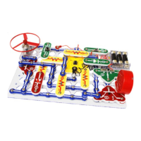
About Your Snap Circuits
®
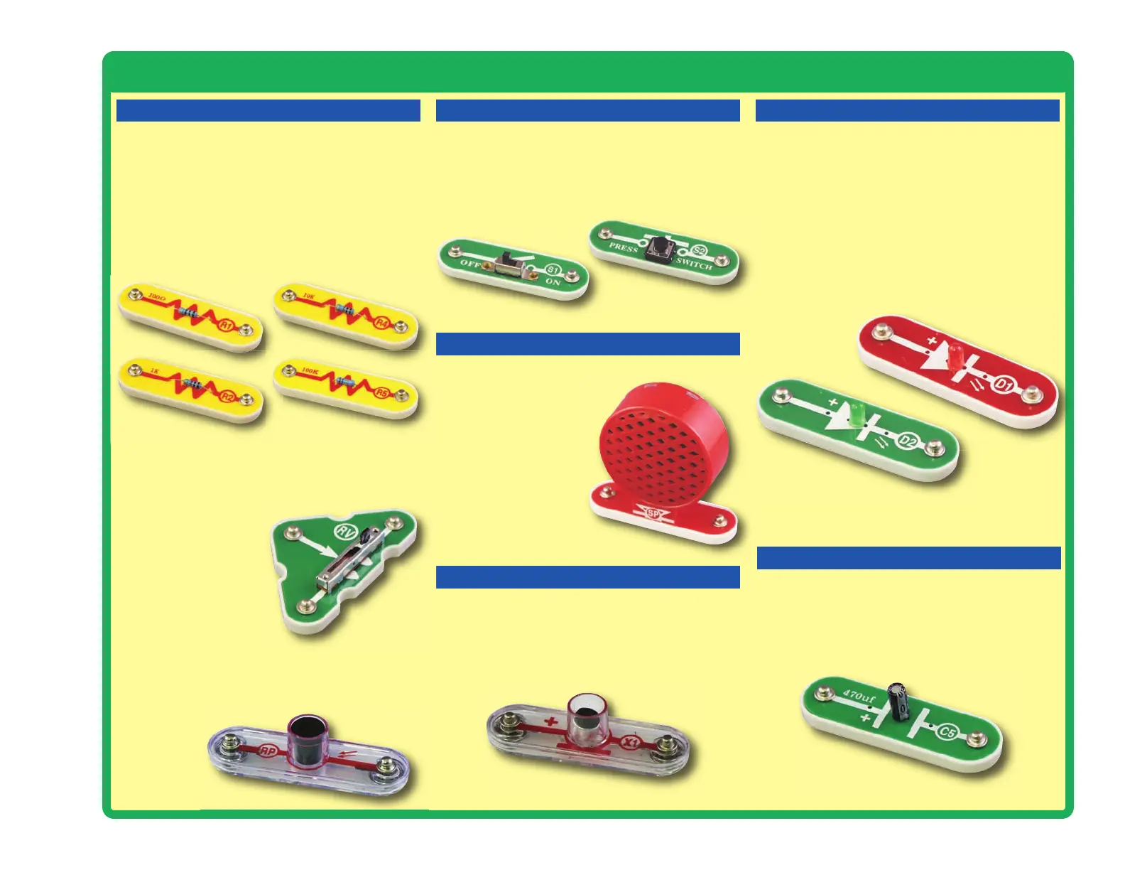
XP Parts
RESISTORS
MICROPHONE
SPEAKER
SLIDE & PRESS SWITCHES RED & GREEN LEDs
CAPACITOR
Resistors (R1, R2, R4, & R5)
Resistors “resist” the flow of electricity and are
used to control or limit the current in a circuit.
Snap Circuits
®
XP includes 100W (R1), 1kW (R2),
10kW (R4), and 100kW(R5) resistors (“K”
symbolizes 1,000, so R4 is really 10,000W).
Materials like metal have very low resistance
(<1W), while materials like paper, plastic, and air
have near-infinite resistance. Increasing circuit
resistance reduces the flow of electricity.
The slide & press switches (S1 & S2) connect
(pressed or “ON”) or disconnect (not pressed or
“OFF”) the wires in a circuit. When ON they have no
effect on circuit performance. Switches turn on
electricity just like a faucet turns on water from a pipe.
Slide & Press Switches (S1 & S2)
The speaker (SP) converts electricity into sound
by making mechanical
vibrations. These vibrations
create variations in air
pressure, which travel
across the room. You
“hear” sound when your
ears feel these air
pressure variations.
Speaker (SP)
The microphone (X1) is actually a resistor that
changes in value when changes in air pressure
(sounds) apply pressure to its surface. Its
resistance typically varies from around 1kW in
silence to around 10kW when you blow on it
Microphone (X1)
The photoresistor (RP) is a light-sensitive
resistor, its value changes from nearly infinite in
total darkness to about 1000W when a bright light
shines on it.
Photoresistor (RP)
The adjustable resistor (RV) is a 50kW resistor
but with a center tap that can be adjusted
between 200W and 50kW.
Adjustable Resistor (RV)
The 470mF capacitor (C5) can store electrical
pressure (voltage) for periods of time. This
storage ability allows it to block stable voltage
signals and pass changing ones. Capacitors are
used for filtering and delay circuits.
Capacitor (C5)
The red & green LED’s (D1 & D2) are light
emitting diodes, and may be thought of as a
special one-way light bulb. In the “forward”
direction, (indicated by the “arrow” in the symbol)
electricity flows if the voltage exceeds a turn-on
threshold (about 1.5V for red and a little higher
for green); brightness then increases. A high
current will burn out the LED, so the current must
be limited by other components in the circuit.
LED’s block electricity in the “reverse” direction.
LED’s (D1 & D2)
 Loading...