Do you have a question about the Elenco Electronics ST-751 and is the answer not in the manual?
Overview of the signal tracer project and assembly expectations.
Check all components against the parts list before assembly.
Guidelines for proper soldering iron use and solder application for good joints.
General instructions for installing components on the PC board.
Instructions for installing various resistors based on part number and color code.
Steps for installing the diode (D1) and the 8-pin IC socket (U1).
Guide for installing disc and electrolytic capacitors, noting polarity.
Instructions for mounting transistors (Q1, Q2) and the LED (D2).
Steps for installing the slide switch (S1), probe tip, and earphone jack.
Guidance on preparing the power cord and connecting it to the PC board.
Instructions for fitting the PC board into the case and attaching the gain control knob.
Verifying LED operation and hearing a tone in the earphone.
Using an amplifier or radio to trace signals by injecting the test tone.
Using the probe tip to pick up signals from different stages.
Explanation of the circuit's squarewave oscillator, amplifier, and voltage control.
Technical details including impedance, signal level, and voltage requirements.
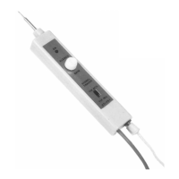
Visual representation of the signal tracer's electronic circuitry.
Steps to diagnose and resolve common issues like LED not lighting or no sound.
Contact information and procedures for obtaining assistance or repairs.
| Category | Test Equipment |
|---|---|
| Model | ST-751 |
| Manufacturer | Elenco Electronics |
| DC Voltage Ranges | 0.1V, 0.5V, 2.5V, 10V, 50V, 250V, 1000V |
| AC Voltage Ranges | 10V, 50V, 250V, 1000V |
| DC Current Ranges | 50µA, 2.5mA, 25mA, 250mA |
| Resistance Ranges | Rx1, Rx10, Rx100, Rx1k, Rx10k |
| Continuity Test | Yes |
| Transistor hFE Test | Yes |
| Impedance | 20kΩ/V DC, 9kΩ/V AC |
| Weight | 0.5 lbs |
| Type | Analog Multimeter |
| Power Supply | Battery operated |