-3-
Step-by-Step Assembly Instructions
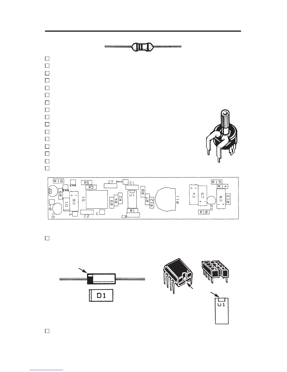
Refer to Figure 1, install and solder the following resistors.
R1 100kW 5% 1/4W brown-black-yellow-gold
R2 100kW 5% 1/4W brown-black-yellow-gold
R3 10kW 5% 1/4W brown-black-orange-gold
R4 180kW 5% 1/4W brown-gray-yellow-gold
R5 6.8kW 5% 1/4W blue-gray-red-gold
R6 100W 5% 1/4W brown-black-brown-gold
R7 220kW 5% 1/4W red-red-yellow-gold
R8 4.7kW 5% 1/4W yellow-violet-red-gold
R9 10kW 5% 1/4W brown-black-orange-gold
R10 1kW 5% 1/4W brown-black-red-gold
R12 47kW 5% 1/4W yellow-violet-orange-gold
R13 2.7kW 5% 1/4W red-violet-red-gold
R14 3.9kW 5% 1/4W orange-white-red-gold
R15 10kW 5% 1/4W brown-black-orange-gold
R16 220W 5% 1/4W red-red-brown-gold
R11 Trim Pot 220k
W
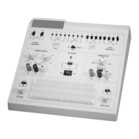
Figure 1 - Top Legend
Install and solder D1, the 1N5234 diode. Note: the diode has polarity
as indicated by the band. Mount the diode with the band corresponding
to the PC board marking as shown in Figure 2.
Install and solder the 8-pin IC soc
ket (U1). Carefully install the LM-385
IC (see Figure 3).
Be sure that the notch is in the correct direction as
sho
wn in Figure 1.
Trim Pot
Band
Figure 2 Figure 3
Notch