Theory of Operation
The diagram on the back cover shows the schematic diagram of the
signal tracer. Its main component is the dual op-amp LM-358. The first
section serves as a squarewave oscillator. Positive feedback is through
resistor R3. The frequency of oscillation is controlled by resistor R4 and
capacitor C1. These components cause the op-amp to oscillate at a
frequency of about 1000Hz. Resistors R1 and R2 are used to bias the
input. Resistors R5 and R6 divide the signal to give an output of 75mV
across the 100W impedance. The squarewave is rich in harmonics which
extend into the AM and FM band of your radio. This allows signal tracing
of AM, RF, and IF stages, and for testing of IF circuits in most FM radios.
The second section of the op-amp is designed to be a variable amplifier.
The input impedance of this amplifier is 100,000W. The gain of the
amplifier is adjustable between 1 to 50 times, depending on the setting of
trim pot R11. Resistors R7 and R8 bias the input circuit with C4 serving
as a bypass capacitor, and C3, the input capacitor. The output of the
amplifier is connected through capacitor C9, transistor Q2, and resistor
R16 to the earphone jack.
Transistor Q1 and the associated components are the voltage control
circuit. Diode D1 is a 5.6V zener, allowing transistor Q1 to produce a
constant 5V output. The circuit is capable of handling input voltages of
between 5 to 40V.
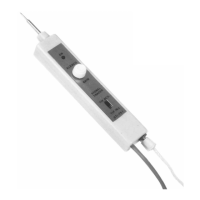
Switch S1 allows the choice of the probe tip to serve as the output of the
oscillator signal, or as the pick up for the test signal.
-8-