2.9
General functional description
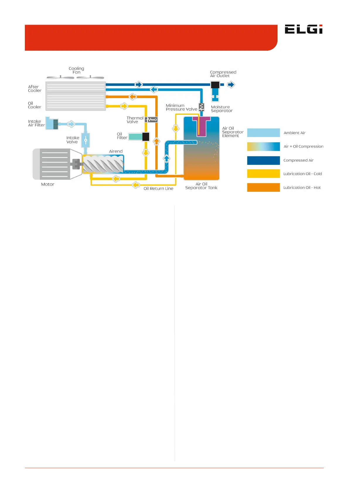
2.4.1 Air circuit
The atmospheric air enters into the airend through the air
intake system. The intake filters (pre filter and air filter)
prevents the entry of foreign particles (such as dust) into
the airend. The intake valve regulates the amount of air
sucked into the airend. The opening and closing of the
intake valve are controlled by the pneumatic pulse line
actuated by an electrically controlled solenoid valve. The
clog indicator fitted in the air filter turns red when the
filter is clogged.
The filtered air enters into the airend where it mixes with
the injected oil. The injected oil acts as a coolant to
maintain optimum temperature. It also seals the leaks
between the rotors and the housing and lubricates the
bearings and gears. The airend consists of two counter-
rotating intermeshed helical screws - the male and the
female rotors - which are driven by electric motor. The air
-oil mixture is trapped between the rotors of the airend
and is progressively compressed.
After being compressed, the air-oil mixture enters with
high velocity into the air-oil separator tank where it
undergoes a unique 3 stage separation process which
removes maximum oil content. This highly efficient 3 stage
separation process uses the impact velocity of air-oil
mixture along with centrifugal action, which makes the
mixture very lean. The final stage of this separation
consists of passing the lean mixture through the air-oil
separator element which leaves the air with an oil content
of < 1 ppm.
The oil separated and collected in this element is then
returned to the airend through the oil return line. The air
passes through a minimum pressure valve (MPV). It
maintains a minimum differential pressure which is
required for circulation of oil within the compressor unit.
The compressed hot air is cooled in the after cooler and is
separated of any moisture content by the moisture
separator. The cooled and moisture free compressed air is
now discharged to the external receiver, ready to be used.
2.4.2 Oil circuit
The oil in the air-oil separation tank after being separated
is fed into the airend. The oil either gets diverted to the oil
cooler or oil filter or both depending upon the
temperature. The thermal valve governs and controls the
oil flow path. The oil before being injected into the airend
is filtered. An orifice is provided in oil flow path towards
the airend to control the oil flow. The whole oil circulation
circuit in the compressor is operated solely by the
differential pressure maintained by the minimum pressure
valve (MPV) and doesn't require any additional pump.
2.4.3 Drive system
The airend transmission is powered by an electric
induction motor through a coupling. When the compressor
is turned ON, the motor is started in star mode and takes
6 to 9 seconds to change over to delta mode. During this
period the intake valve remains closed and thus the motor
starts without load. In delta mode, the motor speed
stabilizes, the solenoid valve energizes after 10 seconds of
change-over to reduce load on the motor, the blow down
valve is closes, intake valve opens and the compressor
starts loading. For compressors with variable frequency
drive (VFD), speed of the motor gradually increases within
30 seconds (ramp-up time) while the intake valve remains
in the closed position. This ensures very little starting load.
Next, the intake valve opens and the system starts
building up pressure. An adaptor ring connects the airend
and the motor. It also helps in maintaining the coupling
alignment. The coupling element acts as a safety interlock
and it is the first one to fail when coupling elements
become over loaded. This architecture saves the whole
drive system from failure. Malfunctioning of the coupling
Figure 1. Screw compressor systems - Schematic diagram
Functional description 2.4
 Loading...