5.5
Installation and operation
1. Supply power to the compressor through a dedicated
switch disconnected fuse (SDF) unit of a suitable rating
mounted within 5 m (16.4ft) of the compressor. (This
architecture lets you isolate the compressor).
2. Use HRC (high rupturing current) fuse instead of an
MCCB (moulded case circuit breaker) to avoid possible
contactor and motor failure.
3. Refer to Table 2 for fuse and cable specifications for 208
-230/380/440/460 V, 60Hz, 3-Ph power supplies.
4. Do not use an MCB (miniature circuit breaker) because
the selection of contactors is based on Type-2 co-
ordination.
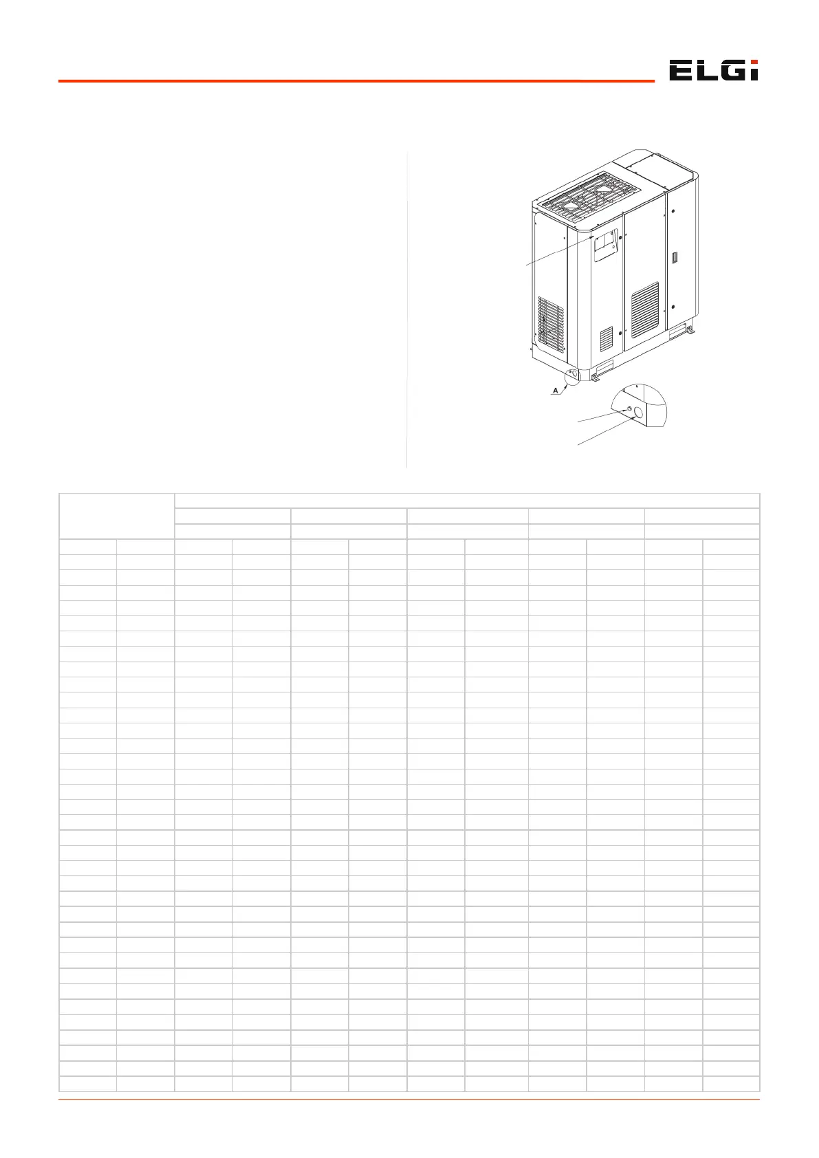
5. Connect the earthling line to the point provided on the
base frame at the side of the compressor and motor.
Volume Flow FAD
NPS Pipe size/ Inside diameter (mm)
1/2 3/4 1 1 1/4 1 1/2
15.80 20.93 26.65 35.05 40.89
(m
3
/min) (cfm) (bar) (psi) (bar) (psi) (bar) (psi) (bar) (psi) (bar) (psi)
0.1 4 0.02 0.22
0.2 7 0.06 0.80 0.01 0.20
0.3 11 0.12 1.69 0.03 0.41 0.01 0.12
0.4 14 0.20 2.88 0.05 0.71 0.01 0.21
0.5 18 0.30 4.35 0.07 1.07 0.01 0.32 0.01 0.08
0.6 21 0.43 6.09 0.10 1.49 0.03 0.45 0.01 0.11
0.7 25 0.57 8.10 0.14 1.99 0.04 0.59 0.01 0.15
0.8 28 0.73 10.38 0.18 2.54 0.05 0.76 0.01 0.19 0.01 0.09
0.9 32 0.90 12.90 0.22 3.16 0.07 0.95 0.02 0.24 0.01 0.11
1.0 35 1.10 15.68 0.27 3.84 0.08 1.15 0.02 0.29 0.01 0.13
1.2 42 0.38 5.38 0.11 1.61 0.03 0.41 0.01 0.19
1.4 49 0.50 7.16 0.15 2.14 0.04 0.54 0.02 0.25
1.6 56 0.64 9.16 0.19 2.74 0.05 0.70 0.02 0.32
1.8 64 0.80 11.40 0.24 3.41 0.06 0.87 0.03 0.40
2.0 71 0.97 13.85 0.29 4.14 0.07 1.05 0.03 0.49
2.2 78 1.16 16.52 0.35 4.94 0.09 1.25 0.04 0.58
2.4 85 1.36 19.40 0.41 5.80 0.10 1.47 0.05 0.68
2.6 92 0.47 6.73 0.12 1.71 0.06 0.79
2.8 99 0.54 7.72 0.14 1.96 0.06 0.91
3.0 106 0.61 8.77 0.16 2.23 0.07 1.03
3.5 124 0.82 11.66 0.21 2.96 0.10 1.37
4.0 141 1.05 14.93 0.27 3.79 0.12 1.75
4.5 159 1.30 18.57 0.33 4.71 0.15 2.18
5.0 177 0.40 5.73 0.19 2.65
5.5 194 0.48 6.83 0.22 3.16
6.0 212 0.56 8.02 0.26 3.71
6.5 229 0.65 9.30 0.30 4.30
7.0 247 0.75 10.67 0.35 4.94
7.5 265 0.85 12.12 0.39 5.61
8.0 282 0.96 13.66 0.44 6.32
8.5 300 1.07 15.28 0.50 7.07
9.0 318 1.19 16.99 0.55 7.86
9.5 335 1.32 18.477 0.61 8.69
10.0 353 1.45 20.64 0.67 9.55
15.0 530 1.42 20.22
5.1.6 Air pipe dimensions
Figure 8. Earthing line of compressor
Power cable entry
Earthing point
CONTROL PANEL
DETAIL-A
 Loading...