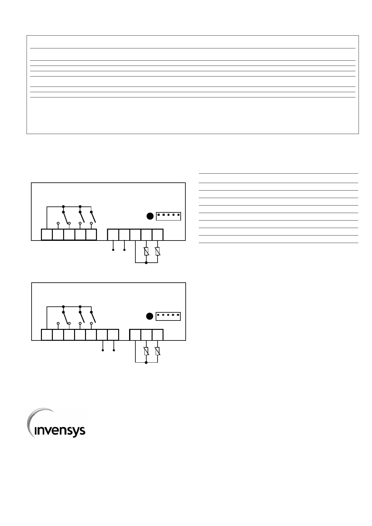
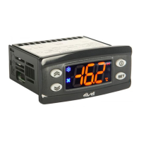
TERMINALS
1 Common relay contact
2 N.A. defrost relay
3 N.C. defrost relay
4 Compressor relay output
5 Fan relay output
6 - 7 Power supply
8 - 9 Probe 2 input (evaporator)
8 - 10 Probe 1 input (thermostat)
A TTL input for Copy Card
NOTE: Default user settings
Invensys Controls Italy s.r.l
via dell'Industria, 15 Zona Industriale Paludi
32010 Pieve d'Alpago (BL) ITALY
Telephone +39 0437 986111
Facsimile +39 0437 989066
Internet http:/www.climate-eu.invensys.com
4/2002 eng
cod. 9IS42066
PAR.
H00 (1)
H42
reL
tAb
UL
dL
Fr
(1) For 230 Va models the default value is 1 (NTC input, see the label on the instrument).
* VALUE column: to be filled manually, with customized settings (if different from the default value).
** LEVEL column: indicates the level of visibility of parameters accessible by PASSWORD (see the related paragraph)
DESCRIPTION
CONFIGURATION (folder with “CnF” label)
Probe type selection, PTC or NTC. 0 = PTC; 1 = NTC.
Evaporator probe present.
reLease firmware. Device version: read only parameter.
tAble of parameters. Reserved: read only parameter.
COPY CARD (folder with “Fpr”label)
Up load. Programming parameter transfer from instrument to Copy Card.
Down load. Programming parameter transfer from Copy Card to instrument
Format. Erasing all data in the copy card.
NOTA BENE: using “Fr” parameter (copy card formatting) the data within the copy
card will be lost permenently. The operation cannot be cancelled.
DEFAULT
0
y
/
/
/
/
/
RANGE
0/1
n/y
/
/
/
/
/
VALUE* LEVEL**
1
1
1
1
1
1
1
U.M.
flag
flag
/
/
/
/
/