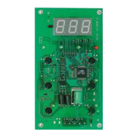
TERMINALS
4 - 5 - 6 SHORT DISTANCE “powered” serial
7 - 8 - 9- 10 LONG DISTANCE serial
11 - 12 programmable digital input 1 (see par. H11)
13 - 14 programmable digital input 2 (see par. H12)
15 - 16 programmable digital input 3 (see par. H13)
17 - 18 programmable digital input 4 (see par. H14)
19 - 20 Probe input 1 (thermostat control)
21 - 22 Probe input 2 (evaporator)
23 - 24 Probe input 3 (display)
OUT 1 (A) N.O. relay output (A) see par. H21 (default 1)
OUT 2 (B) relay output (B) see par. H22 (default 2)
OUT 3 (C) N.O. relay output (C) see par. H23 (default 3)
OUT 4 (D) relay output (D) see par. H24 (default 6)
OUT 5 (E) N.O. relay output (E) see par. H25 (default 7)
OUT 6 (F) N.O. relay output (F) see par. H26 (default 12)
TTL TTL input for Copy Card
optional modules
LONG DISTANCE optional plug-in module for base
board-keyboard connection via LONG DISTANCE serial
1 - 2 - 3 485 serial for TELEVIS
TTL TTL input for connection to Televis system
optional modules
TELEVIS optional plug-in module for Televis
connection via 485 Serial
7/2006 eng
cod. 9IS23095
BASE
BOARD
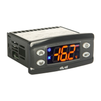
IWP 760 LX BASE BOARD CONNECTIONS
IWP 760 LX Fan Condenser
CONDITIONS OF USE
PERMITTED USE
For safety reasons the instrument
must be installed and used in accor-
dance with the instructions sup-
plied. Users must not be able to
access parts with dangerous voltage
levels under normal operating con-
ditions. The device must be suitably
protected from water and dust
depending on the specific applica-
tion and only be accessible using
special tools (except for the front
keypad). The device can be fitted to
equipment for household use
and/or similar use in the refrigera-
tion sector and has been tested
with regard to safety in accordance
with the European harmonized ref-
erence standards.
It is classified as follows:
• as an automatic electronic control
device to be independently mount-
ed as regards construction;
• as a 1 B type operated control
device as regards its automatic
operating features;
• as a Class A device as regards the
category and structure of the soft-
ware.
UNPERMITTED USE
The use of the unit for applications
other than those described above is
forbidden. It should be noted that
the relay contacts supplied with the
device are functional and therefore
exposed to potential faults.
Any protection devices required to
comply with product requirements
or dictated by common sense due
to obvious safety reasons should be
installed externally.
RESPONSIBILITY AND RESIDUAL
RISKS
Eliwell Controls srl shall not be
liable for any damages deriving
from:
• installation/use other than that
prescribed and, in particular, which
does not comply with the safety
standards specified in the regula-
tions and/or those given herein;
• use on boards which do not guar-
antee adequate protection against
electric shock, water or dust when
assembled;
• use on boards which allow dan-
gerous parts to be accessed without
the use of tools;
• tampering with and/or alteration
of the product;
• installation/use on boards that do
not comply with the standards and
regulations in force.
NOTE
The layout of the base boards in the connection diagram is not to scale and is only
intended to indicate the position of the terminals and modules.
 Loading...