ES 50 – ES 80
36
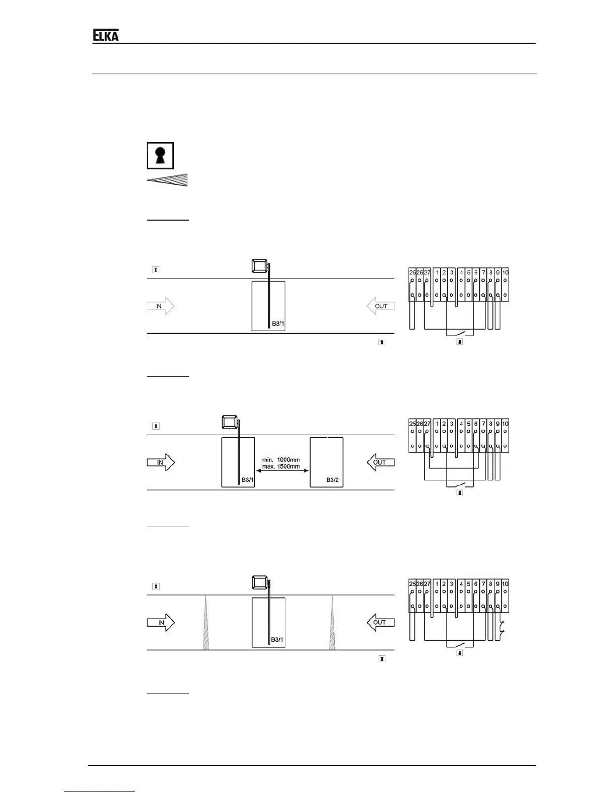
13 Examples for use of loop detectors
B3/2 This loop may be used for opening or for detecting that a vehicle is present
(connected to socket B3 by contacts X1/24 top und X1/24 bottom).
B3/1 This loop is for the safety only and is placed under the barrier boom (connected to
socket B3 by contacts X1/23 top und X1/23 bottom).
B2
This loop is for opening only (connected directly to socket B2 – contacts 7 and 8).
Push button, key switch, card reader, coin selector, etc.
Photo-cell
Example 1 – (for 1-channel loop detector on socket B3)
Entrance and Exit – opening with push button. Safety and closing with loop detector on socket B3/1 (all
jumpers at default settings). Remove red jumper of socket B3 and jumper between the terminals 27
bottom and 6 bottom.
Drawing 13
Example 2 – (for 2-channel loop detector on socket B3)
Entrance – opening with a key switch. Safety and closing with both loops B3/1 and B3/2. Exit - opening
with loop B3/2. Safety and closing with both loops (all jumpers at default settings). Remove red jumper
of socket B3 and jumper between the terminals 25 top and 25 bottom. DIP S8 = ’on’.
Drawing 14
Example 3 – (for 1-channel loop detector on socket B3)
Entrance and Exit – opening with a coin selector. Safety with photo-cells and loop B3/1. Automatic
closure when the time to stay open has elapsed. Remove the jumper between 9 top and 9 bottom and
connect the safety contact of the photo-cells to them (all jumpers at default settings). Remove red
jumper of socket B3 and jumper between the terminals 27 bottom and 6 bottom.
Drawing 15
Example 4 – (for 2-channel loop detector on socket B3)
Entrance and Exit - with card reader. The loop B3/2 allows use of the card reader only when a vehicle
is on the loop. The loop B3/1 is for safety and closing when a vehicle leaves the loop. The jumpers are
at the default settings. Remove the jumper between terminals 6 bottom and 27 bottom and connect the
contact from the card reader here. Remove the red jumper of socket B3 (between terminals 6 and 10).
 Loading...