P 2500 - P 500
4
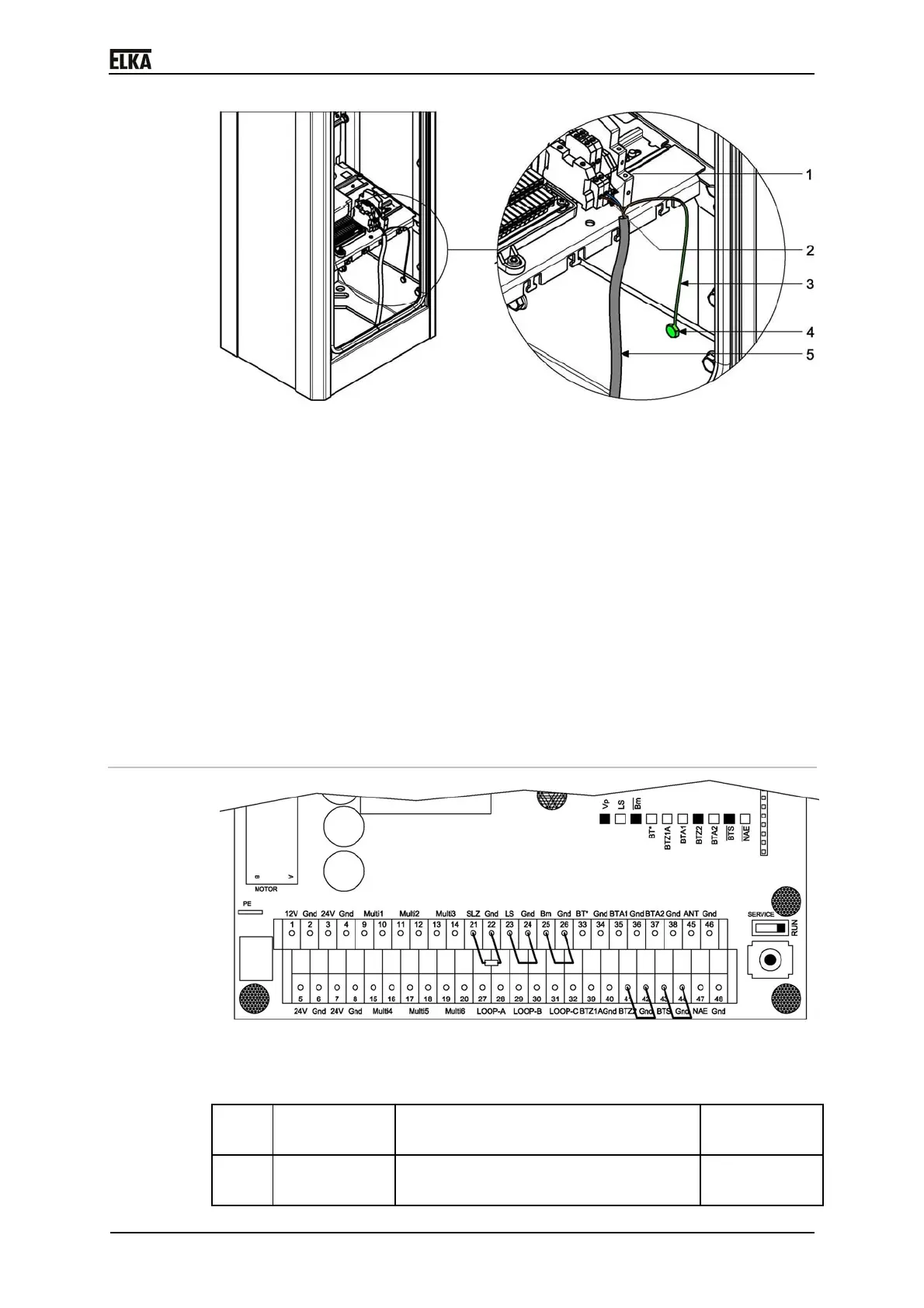
Drawing 32
1 Lead N
2 Lead L1
3 Lead PE
4 Protective conductor terminal (PE), green, thread M6
5 Mains lead
2. Lay the mains lead to the terminals using the shortest possible distance.
Make sure the mains lead does not touch the moving mechanics.
3. Connect the protective conductor PE to the green protective conductor
terminal (PE).
4. Connect the leads L1 and N of the mains lead to the terminals.
5. Fasten / Secure the mains lead to the provided flaps using cable ties.
8.3 Controller terminal row
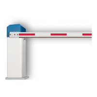
Drawing 33
The following control inputs have to be bridged or occupied with contact (NC)
for operation:
1. Terminals
23 + 24
Photoelectric barrier (LS) NC contact or
bridge
2. Terminals
25 + 26
Boom missing contact (Bm) NC contact or
bridge