P 2500 - P 500
41
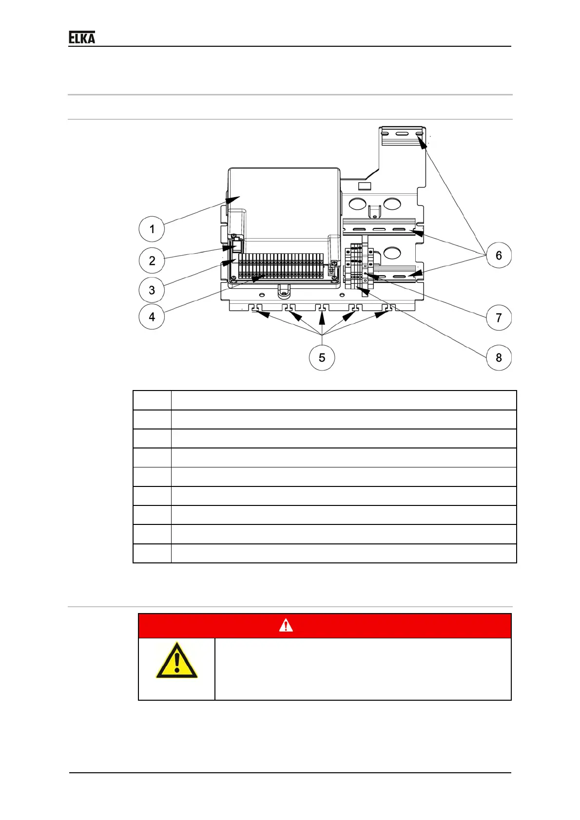
8 Terminal row
8.1 Interior view
Drawing 30
Pos. Description
1 Controller MO 24 (with housing and cover)
2 Supply voltage 24VDC
3 Motor connection
4 Terminal row
5 Fixing clamp for power- and signal lines
6 Top hat rail for accessories (optional or on-site)
7 On-off switch
8 Main terminals (L1, N and PE)
Table 8
8.2 Mains connection
DANGER!
Danger through voltage!
Danger of an electric shock.
Only certified electricians should connect the barrier to
the mains supply.
 Loading...